Method and system for engine braking in an internal combustion engine using a stroke limited high pressure engine brake

a technology of high-pressure engine and internal combustion engine, which is applied in the direction of machines/engines, output power, electric control, etc., can solve the problems of reducing braking power, prior art methods and systems do not disclose vgt to improve bleeder braking performance, and achieve the effect of improving the performance of the engine braking system and the performance of the bleeder braking system

Inactive Publication Date: 2005-03-15
DIESEL ENGINE RETARDERS
View PDF20 Cites 37 Cited by
  • Summary
  • Abstract
  • Description
  • Claims
  • Application Information

AI Technical Summary

Benefits of technology

It is an object of the present invention to improve performance of an engine braking system using turbocharger control.
It is another object of the present invention to improve performance of a bleeder brake system using VGT.
Another object of the present invention is to control the pressure gradient across a VGT turbine in ...

Problems solved by technology

Despite these advantages, however, bleeder type engine brakes have not been widely used because they typically produce less braking power than the compression-release type brakes in heavy duty diesel engines with a conventional fixed geometry turbocharger (FGT).
This reduced braking power occurs especially at low and moderate engine speeds.
The prior art methods and systems do not disclose incorporating VGT to improve bleeder braking performance.
For example, Faletti et al., U.S. Pat. No. 6,148,793 (Nov. 21, 2000), discloses a compression-release type braking system utilizing a variable geometry turbocharger, but does not disclose a bleeder braking system using VGT for optimizing engine braking.
The >890 patent does not, however, disclose a system and method utilizing VGT to control exhaust back pressure for improving bleeder braking performance.
Also, Price et al., U.S. Pat...

Method used


Image

  • Method and system for engine braking in an internal combustion engine using a stroke limited high pressure engine brake
  • Method and system for engine braking in an internal combustion engine using a stroke limited high pressure engine brake
  • Method and system for engine braking in an internal combustion engine using a stroke limited high pressure engine brake

Examples


Embodiment Construction

Reference will now be made in detail to a preferred embodiment of the engine system 10 of the present invention, an example of which is illustrated in the accompanying drawings.

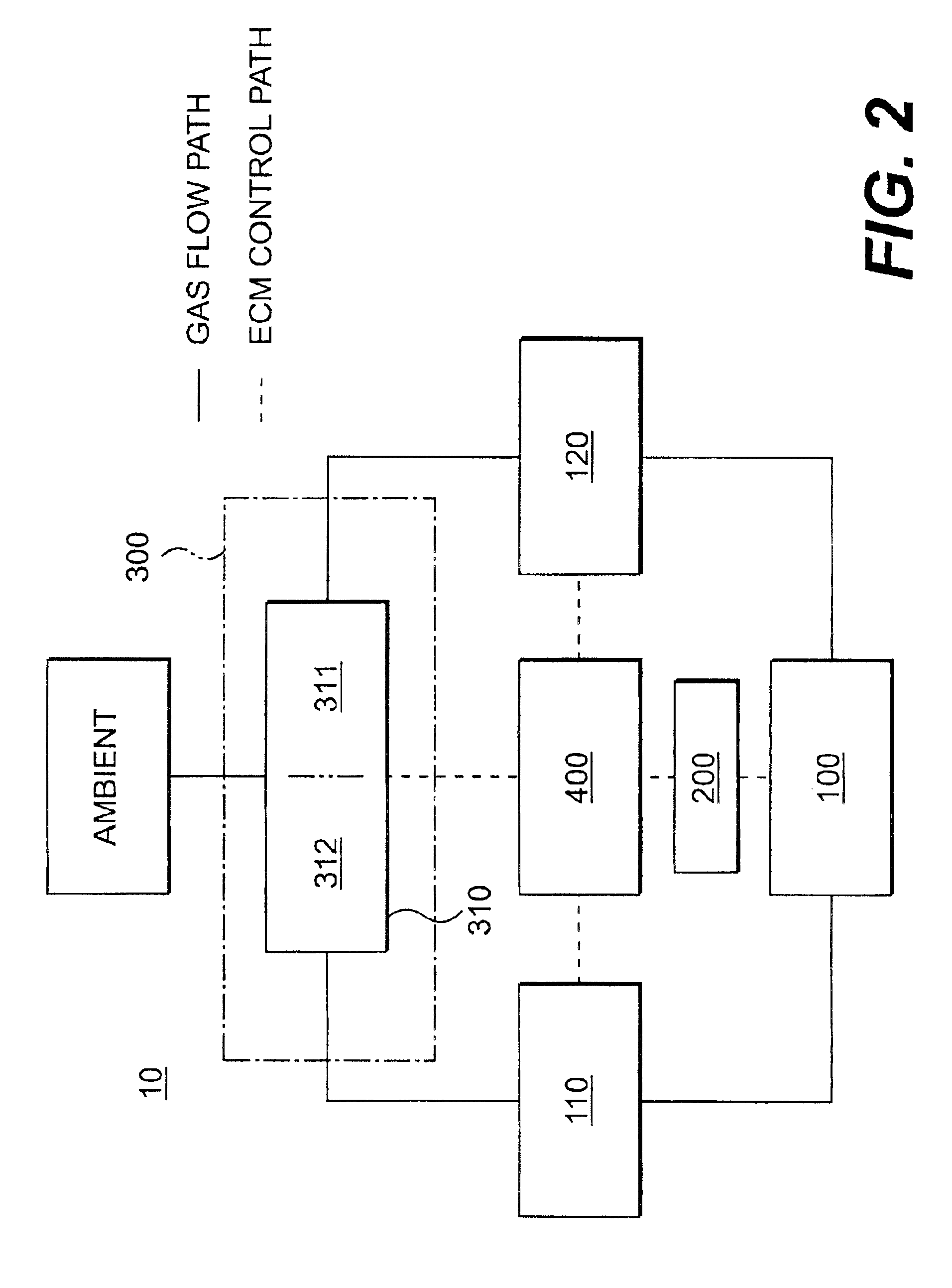
FIG. 2 illustrates the general relationship of engine components in the internal combustion engine system 10. The engine system 10 includes an engine block 100 connected to an intake manifold 110 and an exhaust manifold 120. The engine block 100 includes at least one intake and at least one exhaust valve (not shown). The engine system 10 further includes a valve actuation subsystem 200, pressure regulation means 300, a turbocharger 310, and engine control means 400.

The actuation of the exhaust valve and / or the intake valve of the present invention can be controlled as required by the valve actuation subsystem 200. In the preferred embodiment of the present invention, the valve actuation subsystem 200 opens the at least one engine valve to produce a bleeder braking event. It is contemplated, however, that the ...


PUM


Abstract

The present invention is directed to an engine braking assembly and method for producing a bleeder braking event in an engine having at least one engine valve, at least one engine cylinder, and intake and exhaust manifolds. The engine braking assembly comprises an engine housing, having a hydraulic circuit formed therein; a high-pressure fluid source adapted to store high-pressure fluid therein; a valve for controlling the flow of the high-pressure fluid, in communication with the high-pressure fluid source through the hydraulic circuit; a control device for selectively controlling the valve; and a valve actuation assembly in communication with the valve through the hydraulic circuit, wherein the valve actuation assembly receives the high-pressure fluid through the valve and wherein the hydraulic force created by the high-pressure fluid actuates and holds open the at least one engine valve to produce the bleeder braking event.

Description

FIELD OF THE INVENTIONThe present invention relates generally to a system and method for engine braking in internal combustion engines. In particular, the present invention relates to an engine braking system and method for producing main, compression-release, bleeder, exhaust gas recirculation, and / or other auxiliary engine valve events using a stroke-limited, high-pressure engine brake.BACKGROUND OF THE INVENTIONFlow control of exhaust gas through an internal combustion engine has been used in order to provide vehicle engine braking. Generally, engine braking systems may control the flow of exhaust gas to incorporate the principles of compression-release type braking, exhaust gas recirculation, exhaust pressure regulation, and / or bleeder type braking.The operation of a compression-release type engine brake, or retarder, is well known. During engine braking, the exhaust valves may be selectively opened to convert, at least temporarily, a power producing internal combustion engine i...

Claims


Application Information

Patent Timeline
IPC IPC(8): F02D21/00F02D41/00F02D23/00F02D21/08F02D9/06F02B37/24F02D9/00F01L13/06F02M25/07F02D13/04F02B37/12F02D9/02F02D13/02
CPCF01L13/06F02B37/24F02D9/06F02D13/0276F02D13/04F02D23/00F02D41/0007F02D41/1448F02M25/0709F02M25/0713F02M25/0752Y02T10/144F01L2760/004F01L2800/00F02D9/02F02D41/0047F02M25/0707F02M25/071F01L2105/00F02M26/01F02M26/05F02M26/06F02M26/07F02M26/10F01L2305/00Y02T10/12
Inventor RUGGIERO, BRIANFUCHS, NEILYANG, ZHOU
Owner DIESEL ENGINE RETARDERS
Why Eureka
Try Eureka