Thermal-pressure relief device

Inactive Publication Date: 2005-03-15
BUEHRLE II HARRY W
View PDF6 Cites 40 Cited by
  • Summary
  • Abstract
  • Description
  • Claims
  • Application Information

AI Technical Summary

Benefits of technology

The present invention overcomes this problem by increasing the bonding area of the amalgam on the blow out member specifically on the underside or bottom of the member while reducing the pressure area of the contained fluid on the member relative to the relief orifice. The fluid within the pressure vessel has basically no direct contact with the low melting alloy. It should be noted, that traces of the amalgam may be inadvertently exposed at the interface of the orifice and the blow out member during the brazing process, however this minuscule amount is insignificant relative to any change, as a whole, in the de-stressing movement of the balance of the amalgam, as such it has been found, that this capillary overrun has no overall detrimental effect on its integrity. This unique embodiment permits the use of time tested commercially available low melting alloys while slowing and reducing the “Creep” failure mode.
Still another object of the invention is directed to existing problems created by incompatible materials. Existing designs allow the low melting alloys or amalgam to be in surface

Problems solved by technology

Mechanical spring loaded membrane pressure relief valves may still be employed with higher pressure composite bottles, however their use does not fulfill the entire safety requirement of a pressure vessel subjected to external heat, such as a fire.
Vessel safety assurance is not achieved with

Method used


Image

  • Thermal-pressure relief device
  • Thermal-pressure relief device
  • Thermal-pressure relief device

Examples


Embodiment Construction

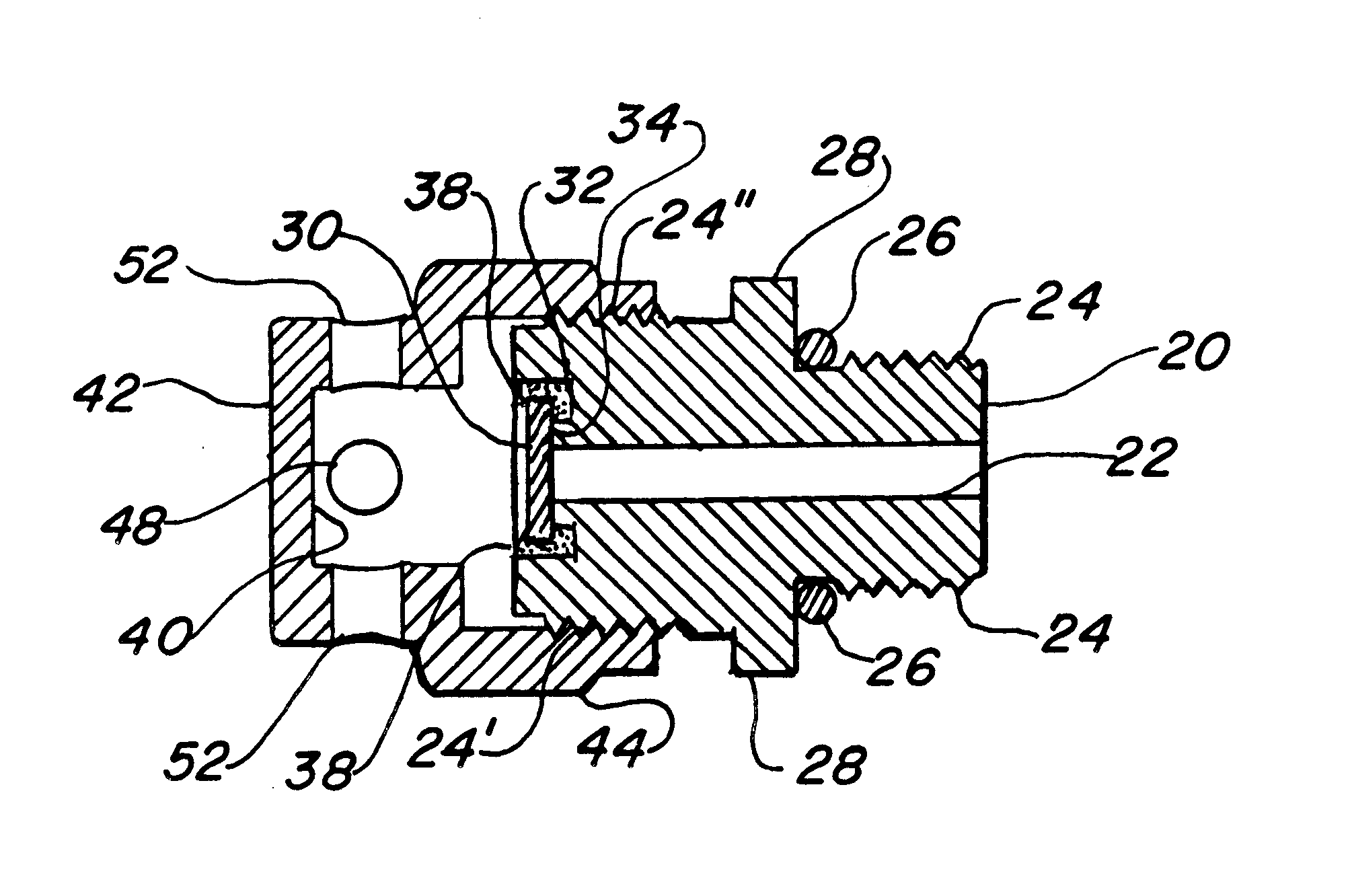
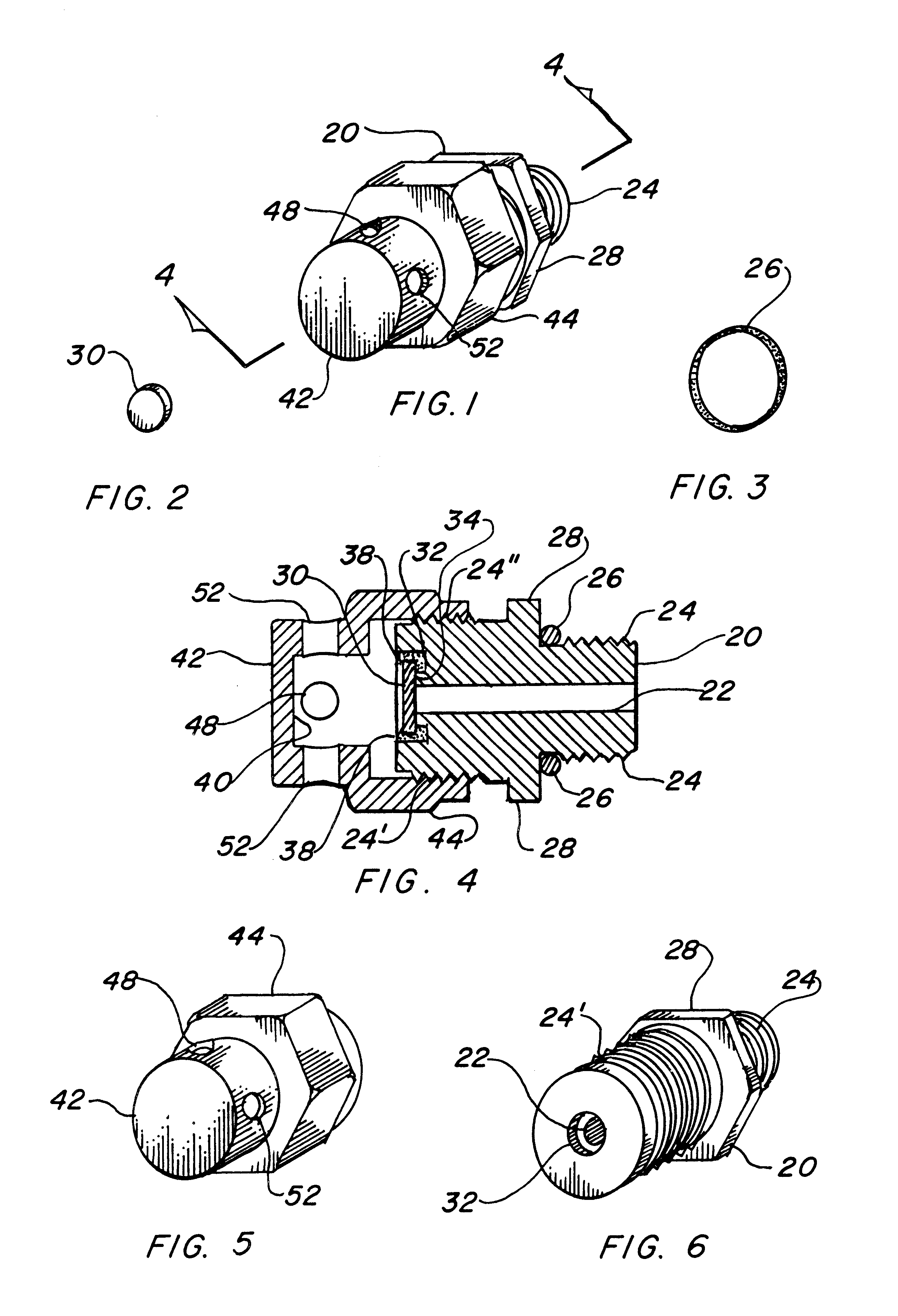
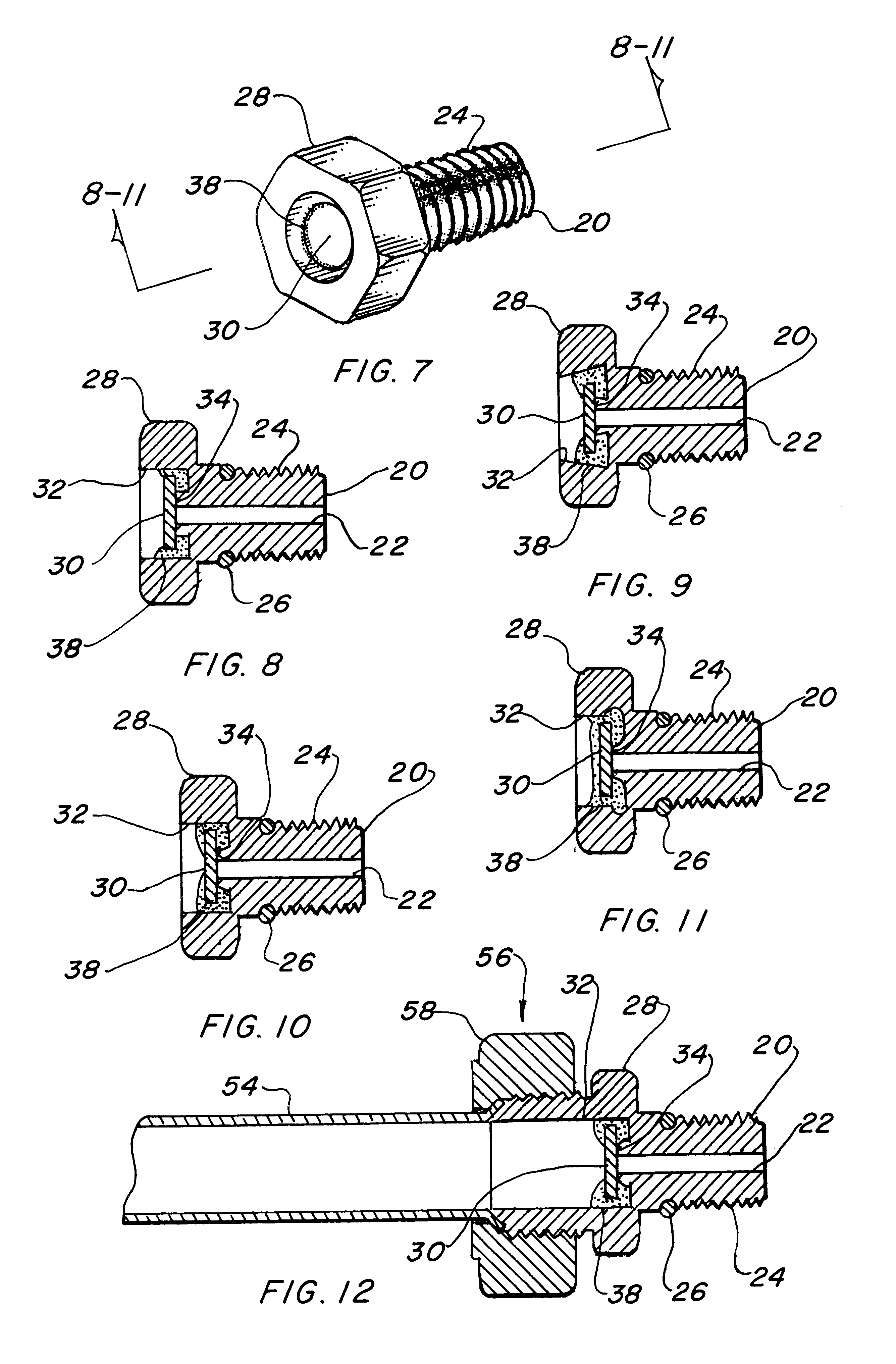
The best mode for carrying out the invention is presented in terms of a preferred embodiment. The preferred embodiment is shown in FIGS. 1 thorough 12 and is comprised of an adapter 20 that contains an orifice 22 in the form of a hole or bore that penetrates the entire longitudinal axis. This orifice 22 is preferably positioned on the centerline, however any location is acceptable provided it continues though allowing communication with the fluid inside the pressure vessel. The adapter 20 has a first end and a second end with the first end configured in such a manner as to be connected through a pressure vessel wall in intimate contact with the working fluid stored inside. The orifice 22 provides a conduit for allowing fluid to escape in the event of excessive pressure within caused by external heat. The second end of the adapter 20 includes a circular recess cavity 32 larger in diameter than the orifice 22. The diameter and tolerance of the orifice may be selected by code requireme...


PUM


Abstract

A thermal-pressure relief device, which has an adapter (20) threaded into the wall of a pressure vessel. The adapter contains an orifice (22) therethrough in line with a recessed cavity (32) which includes a raised stem (34). A blow out member (30) rests on the stem and overlaps the orifice to obstruct communication with the fluid inside the vessel. The blow out member is attached within the cavity by brazing with a filler metal in the form of a temperature responsive amalgam (38), preferably a eutectic alloy. When ambient temperatures are elevated above the melting point of the amalgam the blow out member is released freeing the orifice relieving the pressure within the vessel preventing a sudden structural failure. Optionally a protective cover in the form of a cap (42) with an impact surface (40) contains the blow out member when it separates from the adapter and a number of vents (48) diffuse the fluid from the pressure vessel in a safe direction. Another option for the protective cover is a tube (54) attached to the adapter with fastening means such that when the blow out member is released the conduit provides a safe structurally sound flow path permitting the pressurized fluid to be directed into a safe zone away from the thermal-pressure relief device.

Description

TECHNICAL FIELDThe present invention relates to pressure relief devices in general. More specifically, to an improved device that will relieve pressure within a pressure vessel before high temperature has raised the pressure of the fluid within the vessel to a level which could cause a structural failure, or in a composite vessel which could result in loss of structural integrity.BACKGROUND ARTPreviously, many types of pressure relief devices have been used in endeavoring to provide an effective means for releasing pressure within a vessel. Any pressure vessel that is made to contain a compressed fluid, be it liquid or vapor, has the dangerous potential to explode when the internal pressure increases above the burst strength of the vessel material.The Improvement protects the public from a dangerous situation that could actually kill or maim humans, government agencies have placed stringent requirements on all pressure vessels to include safety devices that relieve the pressure prio...

Claims


Application Information

Patent Timeline
IPC IPC(8): F16K17/38F16K17/36
CPCF16K17/383Y10T137/1812Y10T137/1963
Inventor BUEHRLE, II, HARRY W.
Owner BUEHRLE II HARRY W
Why Eureka
Try Eureka