Burner system employing flue gas recirculation

Inactive Publication Date: 2005-03-15
EXXONMOBIL CHEM PAT INC
View PDF85 Cites 12 Cited by
  • Summary
  • Abstract
  • Description
  • Claims
  • Application Information

AI Technical Summary

Benefits of technology

The present invention is directed to a method and system for reducing NOx emissions from burners of furnaces such as those used in steam cracking. The system includes a furnace including, a burner, the burner including a primary air chamber; a burner tube having a downstream end, an upstream end in fluid communication with the primary air chamber for receiving air, fuel gas or mixtures thereof and fuel and optionally steam, a venturi portion positioned between the downstream end and the upstream end, and a burner tip mounted on the downstream end of the burner tube for combusting the fuel downstream of the burner tip; and a fuel orifice located adjacent the upstream end of the burner tube for introducing fuel into the burner tube; a source

Problems solved by technology

This strategy, known as Selective Catalytic Reduction (SCR), is very costly and, although it can be effective in meeting more stringent regulations, represents a less desirable alternative to improvements in burner design.
In addition, many raw gas burners produce luminous flames.
Since ethylene furnaces are amongst the highest temperature furnaces used in the hydrocarbon processing industry, the natural tendency of burners in these furnaces is to produce high levels of NOx emissions.
However this must be balanced with the fact that radiant heat transfer decreases with reduced flame temperature, while CO emissions, an indication of incomplete combustion, may actually increase as well.
The ability of these burners to gen

Method used


Image

  • Burner system employing flue gas recirculation
  • Burner system employing flue gas recirculation
  • Burner system employing flue gas recirculation

Examples


Embodiment Construction

Although the present invention is described in terms of a burner for use in connection with a furnace or an industrial furnace, it will be apparent to one of skill in the art that the teachings of the present invention also have applicability to other process components such as, for example, boilers. Thus, the term furnace herein shall be understood to mean furnaces, boilers and other applicable process components.

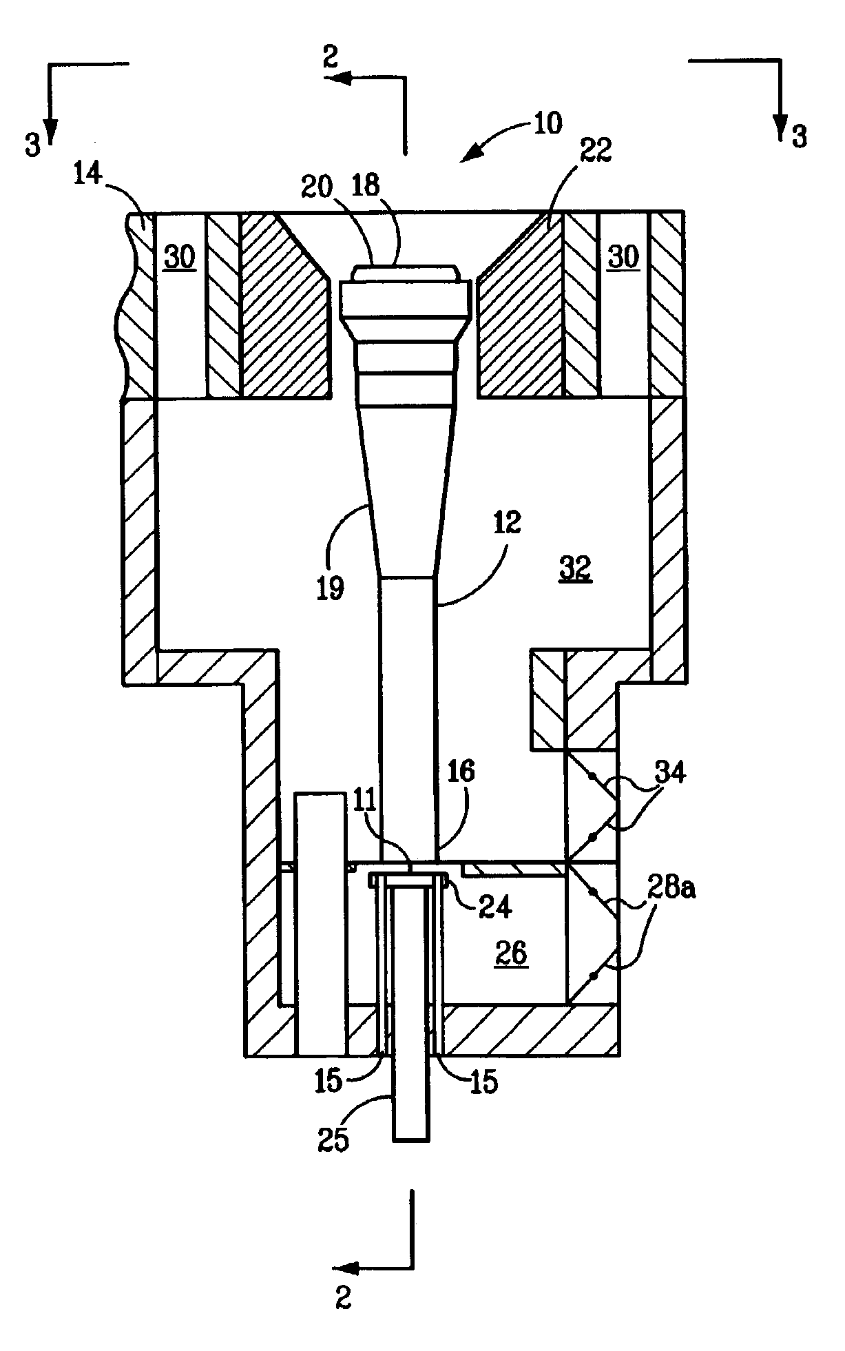
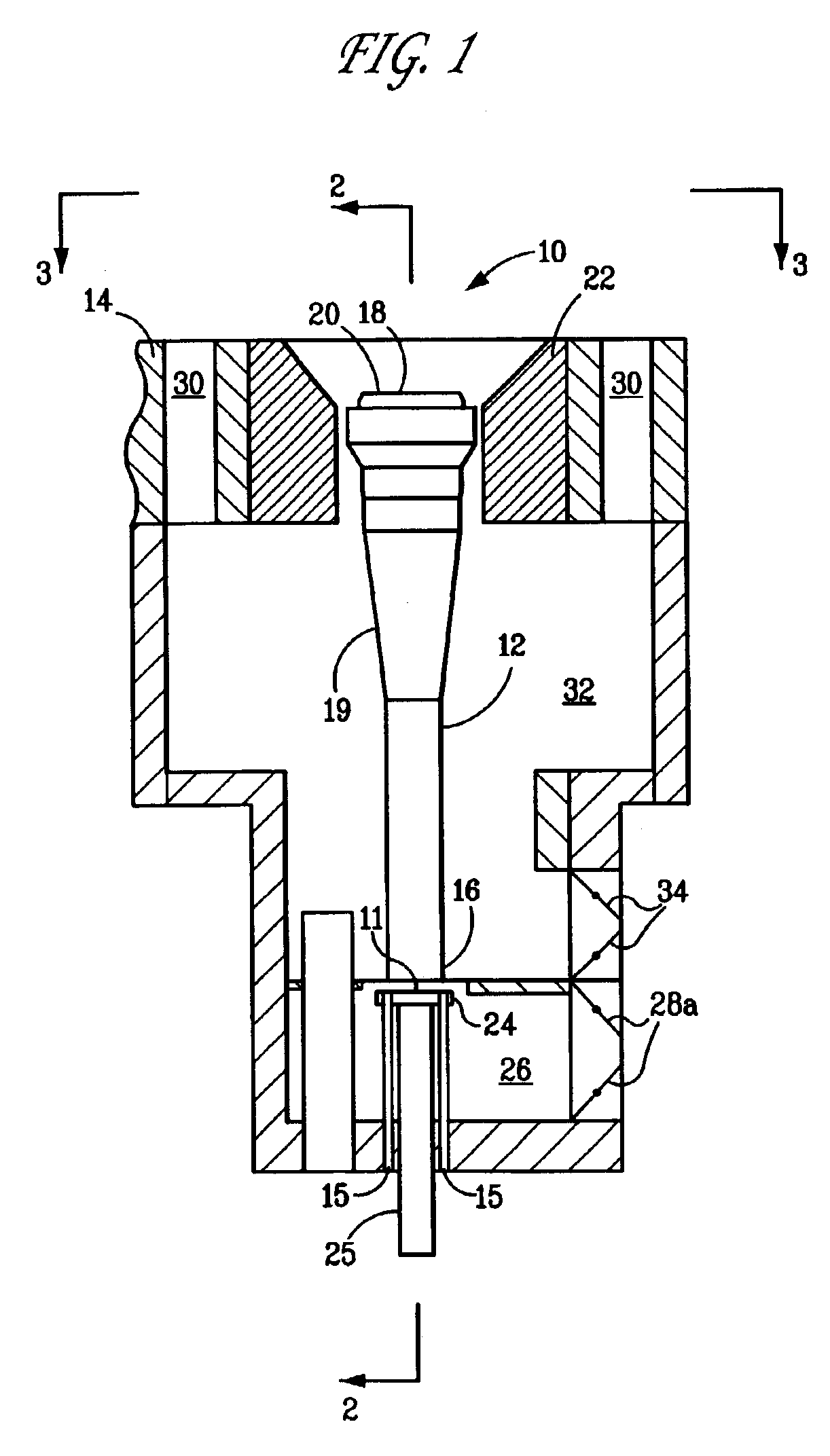
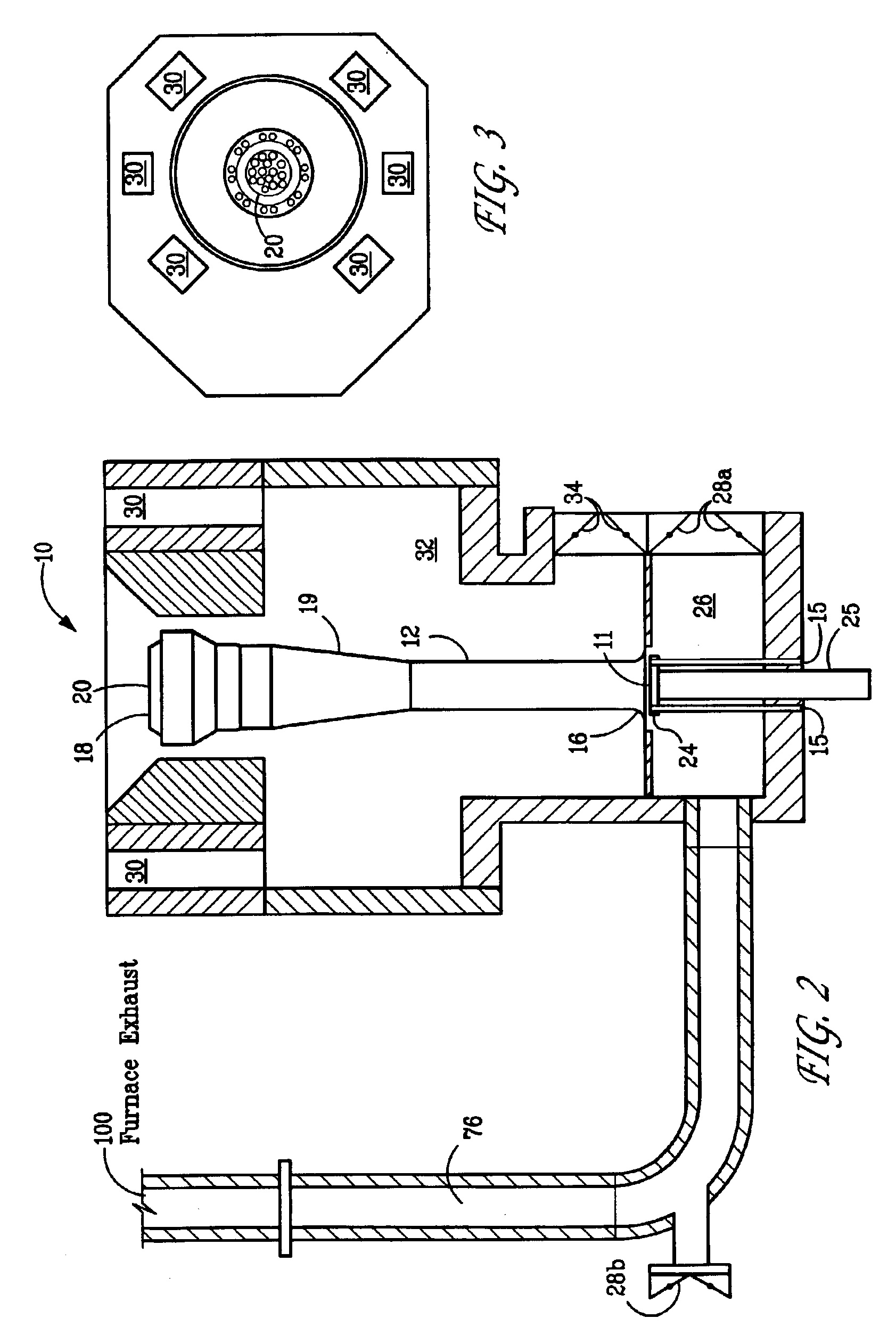
Referring particularly to FIGS. 1-3, a premix burner 10 includes a freestanding burner tube 12 located in a well in a floor 14 of a furnace. The burner tube 12 includes an upstream end 16, a downstream end 18 and a venturi portion 19. A burner tip 20 is located at the downstream end 18 and is surrounded by an annular tile 22. A fuel orifice 11, which may be located within gas spud 24, is at the top end of a gas fuel riser 25 and is located at the upstream end 16 and introduces fuel gas into the burner tube 12. Fresh or ambient air is introduced into a primary air chamber 2...


PUM


Abstract

System for reducing NOx emissions from burners of furnaces such as those used in steam cracking. The system includes a furnace having at least one burner, the at least one burner including a primary air chamber; a burner tube including a downstream end, an upstream end in fluid communication with the primary air chamber for receiving air, flue gas or mixtures thereof and fuel, a venturi portion positioned between the downstream end and the upstream end, and a burner tip mounted on the downstream end of the burner tube adjacent the first opening in the furnace for combusting the fuel downstream of the burner tip; and a fuel orifice located adjacent the upstream end of the burner tube for introducing fuel into the burner tube; a source of flue gas, said source positioned so as to enable the flue gas to achieve a temperature of less than 2000° F. at least one passageway for conducting flue gas from the source to the primary air chamber; and inspirating means, the inspirating means including the venturi portion effective for drawing flue gas from the source, through the at least one passageway and the primary air chamber in response to an inspirating effect of uncombusted fuel exiting the fuel orifice, the uncombusted fuel flowing through the burner tube from its upstream end towards its downstream end, whereby the flue gas is mixed with air at the upstream end of the burner tube prior to the zone of combustion of the fuel.

Description

FIELD OF THE INVENTIONThis invention relates to an improvement in a burner system such as those employed in high temperature furnaces in the steam cracking of hydrocarbons. More particularly, it relates to a system employing flue gas recirculation (FGR) to achieve a reduction in NOx emissions.BACKGROUND OF THE INVENTIONAs a result of the interest in recent years to reduce the emission of pollutants from burners used in large furnaces, burner design has undergone substantial change. In the past, improvements in burner design were aimed primarily at improving heat distribution. Increasingly stringent environmental regulations have shifted the focus of burner design to the minimization of regulated pollutants.Oxides of nitrogen (NOx) are formed in air at high temperatures. These compounds include, but are not limited to, nitrogen oxide and nitrogen dioxide. Reduction of NOx emissions is a desired goal to decrease air pollution and meet government regulations. In recent years, a wide va...

Claims


Application Information

Patent Timeline
IPC IPC(8): F23M11/04F23D14/04F23M5/00F23D14/08F23C9/00F23C6/04F23D14/58F23C6/00F23C7/00F23D14/48F23M11/00F23L7/00F23M5/02
CPCF23C6/045F23C7/008F23C9/00F23M11/042F23D14/58F23L7/005F23M5/025F23D14/08F23C2202/10F23C2900/06041F23D2900/00011
Inventor STEPHENS, GEORGE
Owner EXXONMOBIL CHEM PAT INC
Why Eureka
Try Eureka