Electrocoagulation reaction chamber and method

a technology of electrocoagulation chamber and reaction chamber, which is applied in the direction of manufacturing tools, water/sewage treatment by oxidation, transportation and packaging, etc., can solve the problems of high overall cost of electrocoagulation process to produce clean water, direct cost of electricity is a significant and the cost of maintaining electrodes is another part of the overall cost. , to achieve the effect of improving the structure of the electrocoagulation chamber and facilitating rapid and simple assembly or disass

Inactive Publication Date: 2005-03-15
GEMINI STRATEGIES +1
View PDF5 Cites 47 Cited by
  • Summary
  • Abstract
  • Description
  • Claims
  • Application Information

AI Technical Summary

Benefits of technology

Against the described background, it is therefore a general object of the invention to provide an improved structure for an electrocoagulation chamber, allowing rapid and simple assembly or disassembly, such as for maintenance.

Problems solved by technology

A primary problem in using an electrolytic process to produce clean water is a generally high cost of treatment.
The direct cost of electricity is a significant part of the overall cost.
The cost of maintaining electrodes is another part of overall cost.
However, electrodes also can be fouled or short-circuited by deposit of reaction products.
A fouled electrode becomes prematurely inefficient and can add to the amount of electricity consumed.
Also, it will wear unevenly and will require premature replacement or removal for cleaning, either of which adds to maintenance cost and down-time for the reaction chamber.
Ease of replacing electrodes is significant, both in terms of maintenance cost and the down-time of a reaction chamber.
These are only a few of the considerations that influence design of reaction chamber, which is a complex process.
Later advances in chamber design reveal that edge-to-edge sinuous flow across a rectangle is not uniform.
However, even passing through a full width slot, the liquid stagnates along the edges of the plates, perhaps because of resistance induced by contact with the gasket or spacer located at such edges.
Thus, it appears likely that longitudinal flow over a rectangular plate bounded by a side wall will be non-uniform and will result in fouling of certain areas of the plates.
However, it can be readily seen that such center-to-periphery and periphery-to-center flow will be non-uniform when square treatment chambers are used.
Fouling is likely along the relatively longer flow paths near the corners of all plates in the stack, with resulting uneven wear, poorly predictable process control, higher electricity usage, short circuits, and premature plate replacement or maintenance.
It is evident that circular plates would be no more successful in producing equal length radial flow paths.
Fabricating and assembling a stack of circular plates is likely to be more expensive and will not solve the problems of premature fouling.
Uneven flow paths or stagnant areas are inevitable results.
Circular plates are likely to behave similarly to square plates in suffering prematurely fouled areas.

Method used


Image

  • Electrocoagulation reaction chamber and method
  • Electrocoagulation reaction chamber and method
  • Electrocoagulation reaction chamber and method

Examples


Embodiment Construction

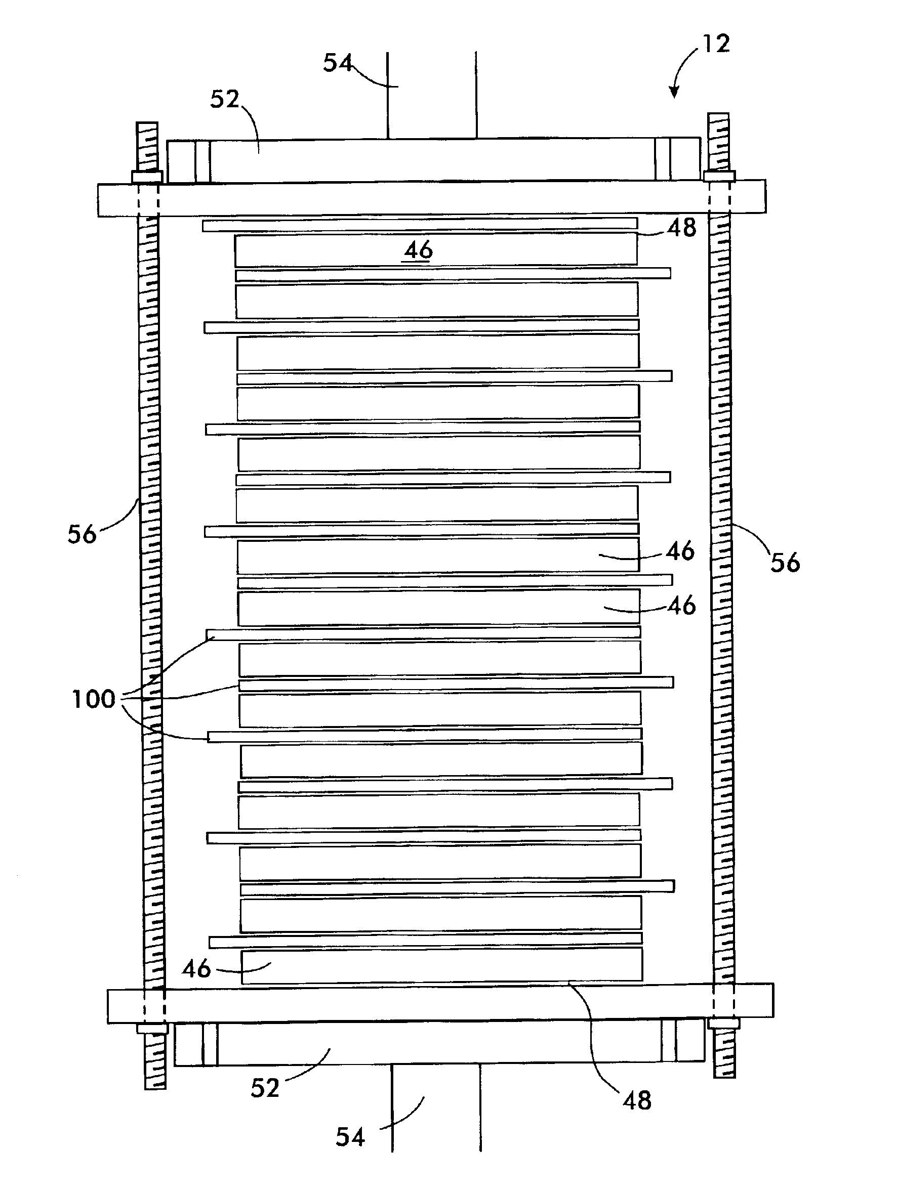
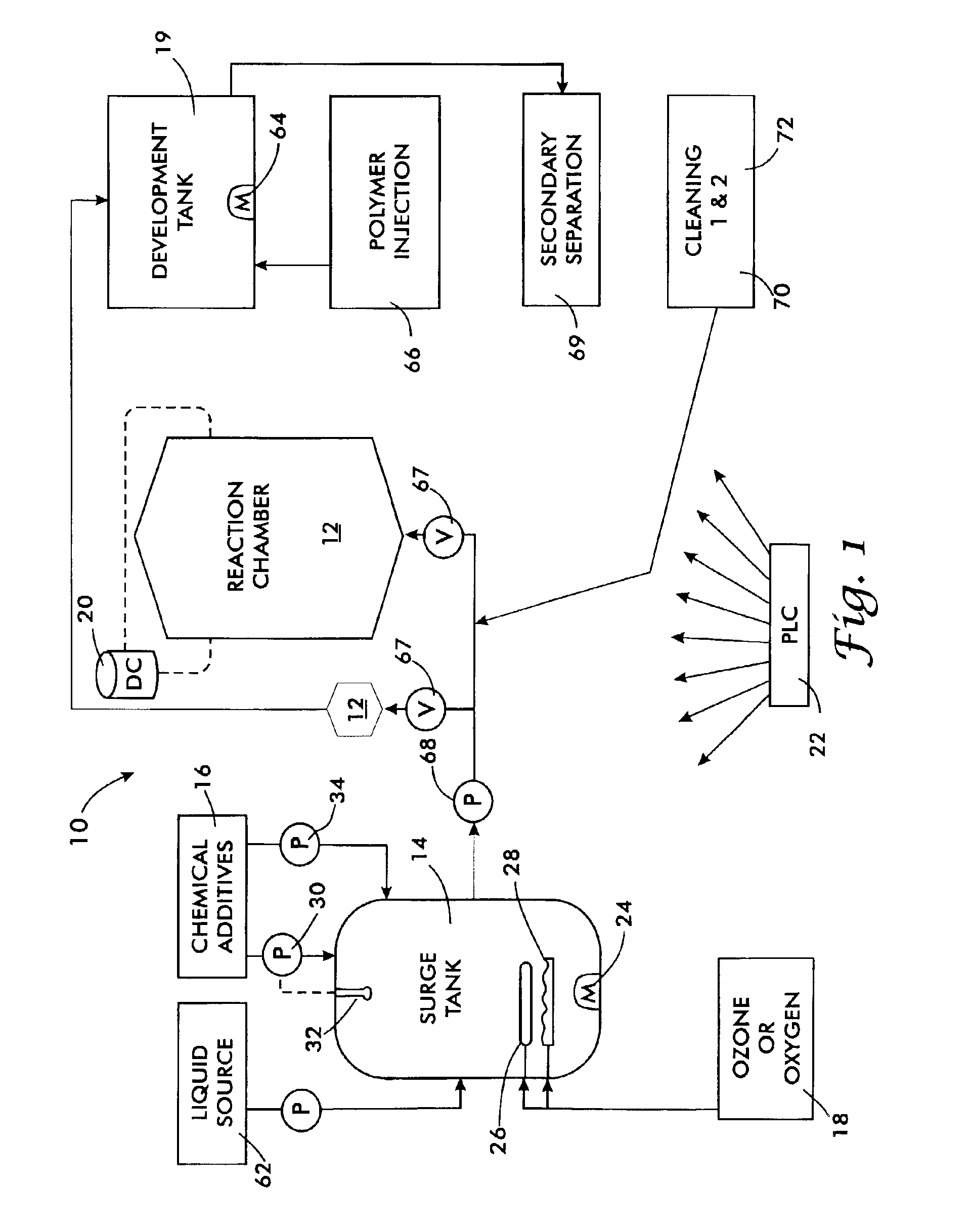
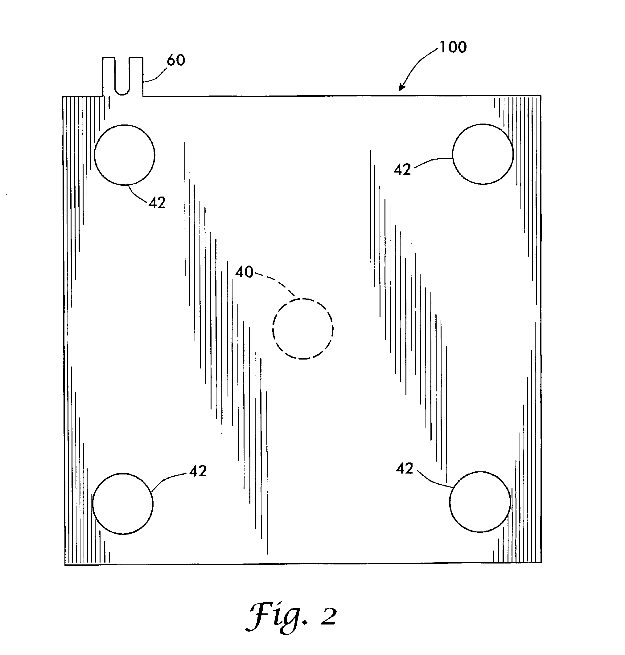
The invention provides a non-fouling, self-cleaning, sinuous flow, electrolytic reaction chamber that is easily assembled, disassembled, and maintained. A reaction chamber having a filter press structure is suitable for establishing and maintaining a stack of electrode plates that define a plurality of sequential treatment chambers or processing zones. The filter press style of reaction chamber is suited use in a system for treating water or other process fluids by electrocoagulation. The non-fouling characteristic of the reaction chamber is achieved by creating streamlined flow paths that confine the process liquid to a highly predictable or known flow path through each zone. Thus, in a streamlined flow path, the available surface area of the electrodes is limited to the shape of a predictable or known flow path characterized by a lack of stagnant areas.

The surface areas of the electrode can be conformed to the predictable or known flow path by several methods. First and preferred,...


PUM

PropertyMeasurementUnit
lengthaaaaaaaaaa
radiusaaaaaaaaaa
aperture radiusaaaaaaaaaa

Abstract

Dielectric rails (112) support an electrode stack (109) that is compressed between end pressure plates (118). The stack is composed of a dielectric spacer (46, 103) forming a central spacer opening, separating a pair of electrode plates (101,102) that each have a different configuration of openings. A first electrode plate (101) of the pair has a central aperture, while the second electrode plate (102) of the pair has peripheral apertures. A compression device such as a hydraulic cylinder (124) compresses the stack, sliding the plates and spacers together to form a pressure-tight reaction chamber (108). When the cylinder is released, any plate or spacer is readily removed from the stack for replacement or maintenance merely by lifting it off the rails. An electric potential can be applied to each electrode plate at a connecting ear (116), which may be a one of the rail guides (116).

Description

TECHNICAL FIELDThe invention generally relates elements used in electrical and wave energy chemistry. More specifically, the invention relates to electrolytic apparatus composed of electrodes with an electrode supporting means consisting of a dielectric gasket or spacer. In a further aspect, the invention relates to an electrolytic apparatus and method that employ parallel plate electrodes to form plural separate treatment chambers or zones, with a feeding or withdrawing means providing a flow of liquid to be treated to the cells.BACKGROUND ARTThe practice of electrolysis upon aqueous solution results in production of water and an agglomerate. The latter can be separated from the water to produce a clean water. This process and its chemistry are well known, and many types of apparatus are used in the practice of it.A primary problem in using an electrolytic process to produce clean water is a generally high cost of treatment. The direct cost of electricity is a significant part of t...

Claims


Application Information

Patent Timeline
Patent Type & Authority Patents(United States)
IPC IPC(8): B01J19/08B01J19/24B01J19/00C02F1/463B01F13/00B01F13/02B01F5/06C02F1/00C02F1/78C02F1/461C02F1/66C02F1/72C02F1/52B01F33/40
CPCB01J19/08B01J19/249C02F1/463B01F5/0602C02F2301/024B01J2219/0813B01J2219/0835B01J2219/0877B01J2219/2453B01J2219/2458B01J2219/246B01J2219/2474B01J2219/249B01J2219/2493B01J2219/2496B01J2219/2498C02F1/46104C02F1/46109C02F1/52C02F1/66C02F1/727C02F1/78C02F2001/46119C02F2201/4611B01F13/02B01F25/42B01F33/40
Inventor GILMORE, F. WILLIAM
Owner GEMINI STRATEGIES
Why Eureka
Try Eureka