Method and apparatus for tunable interferometer utilizing variable air density

a variable air density, interferometer technology, applied in the field of tunable interferometer, can solve the problems of increasing the complexity and difficulty of fabricating reducing the stability and optical throughput of the interferometer, and increasing the difficulty of forming and aligning the interferometer

Inactive Publication Date: 2005-03-15
II VI DELAWARE INC
View PDF9 Cites 50 Cited by
  • Summary
  • Abstract
  • Description
  • Claims
  • Application Information

AI Technical Summary

Benefits of technology

The optical cavity between the parallel reflective or partially reflective surfaces comprises an “air” gap that is filled with air or another gas. The air or gas within the air gap communicates with air or gas outside of the optical cavity but within the enclosure through a hole, opening, slit, slot, etc. in or between the plates or the at least one spacer. The pressure changing mechanism causes changes in the density of air or gas so as to control the refractive index of air or gas within the optical cavity. The change in refractive index produces small precise changes in the optical path length within the optical cavity such that maxima and minima in periodic curves of transmission, reflection or polarization rotation are shifted by precisely controlled amounts. These shifts are utilized, within devices incorporating the air-density-tuned interferometer, to adjust the positions of the transmission, reflection or polarization rotation into correspondence with standard optical channel positions, to provide variable chromatic dispersion for optical channels or to switch or route channels.

Problems solved by technology

Although these methods provide adequate tuning capabilities, they invariably add additional optical components and / or electronic connections to the interferometer, thereby increasing the complexity and difficulty of fabricating and aligning the interferometer and potentially reducing the stability and optical throughput of the interferometer.

Method used


Image

  • Method and apparatus for tunable interferometer utilizing variable air density
  • Method and apparatus for tunable interferometer utilizing variable air density
  • Method and apparatus for tunable interferometer utilizing variable air density

Examples


Embodiment Construction

The present invention provides an improved tunable interferometer apparatus as well as methods and apparatuses for utilizing the tunable interferometer within optical communications networks. The following description is presented to enable one of ordinary skill in the art to make and use the invention and is provided in the context of a patent application and its requirements. Various modifications to the preferred embodiment will be readily apparent to those skilled in the art and the generic principles herein may be applied to other embodiments. Thus, the present invention is not intended to be limited to the embodiment shown but is to be accorded the widest scope consistent with the principles and features described herein.

To more particularly describe the features of the present invention, please refer to FIGS. 1 through 6 in conjunction with the discussion below.

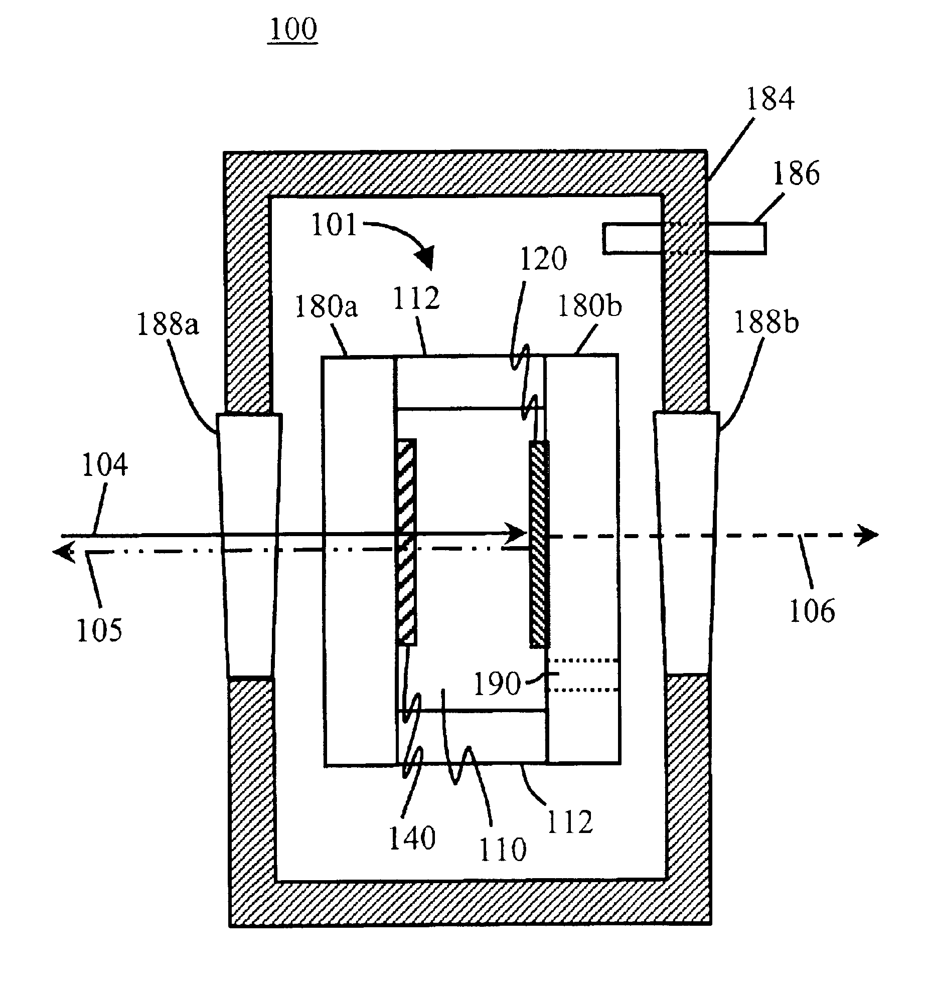
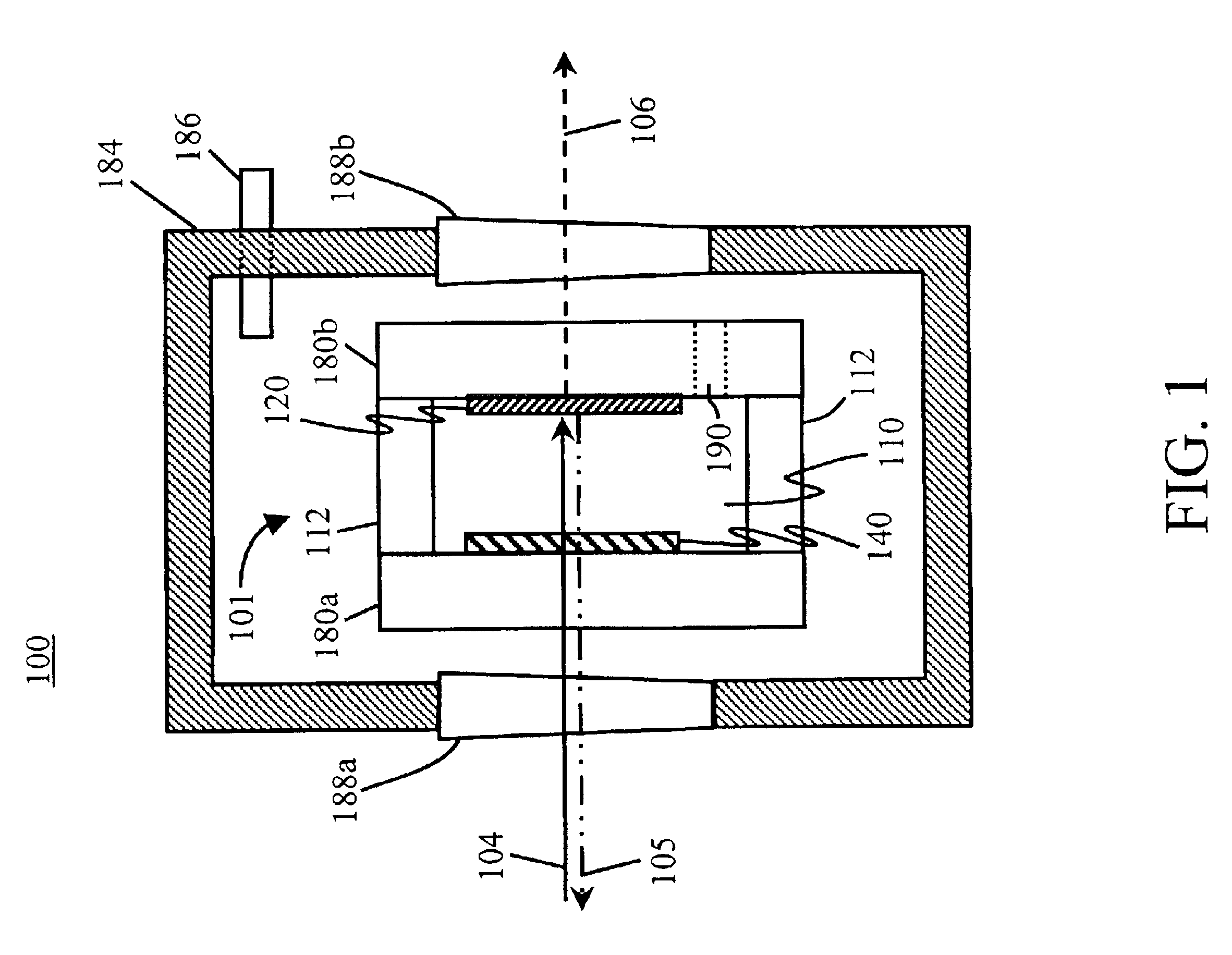
FIG. 1 is an illustration of a first preferred embodiment of an air-density-tuned interferometer in accordance with ...


PUM


Abstract

An air-density-tuned interferometer includes: a hermetically sealed enclosure; a front window coupled to the hermetically sealed enclosure; an interferometer residing within the hermetically sealed enclosure; and a pressure changing device coupled to the hermetically sealed enclosure. The interferometer within the enclosure includes: a first glass plate optically coupled to the front window; a first reflective coating coupled to the first glass plate; a second reflective coating optically coupled to the first reflective coating; a second glass plate coupled to the second reflective coating; and a plurality of spacers coupled to the first and second glass plates, forming an optical interometric cavity therein. The pressure changing device manipulates the gas pressure within the cavity. The air-density-tuned interferometer does not incorporate additional elements into the optical path within the interferometer and that does not disturb or move any of the optical components disposed within or associated with this optical path.

Description

FIELD OF THE INVENTIONThe present invention relates to optical switching, routing, filtering, dispersion compensating, multiplexing and de-multiplexing devices and methods. More particularly, the present invention relates to a tunable interferometer comprising parallel reflective surfaces whose tuning capability is utilized to perform the switching, routing, filtering, dispersion compensation, multiplexing and / or de-multiplexing.BACKGROUND OF THE INVENTIONThe use of optical fiber for long-distance transmission of voice and / or data is now common. As the demand for data carrying capacity continues to increase, there is a continuing need to utilize the bandwidth of existing fiber-optic cable more efficiently. An established method for increasing the carrying capacity of existing fiber cable is Wavelength Division Multiplexing (WDM). In this method, multiple information channels are independently transmitted over the same fiber using multiple wavelengths of light and each light-wave-pro...

Claims


Application Information

Patent Timeline
Patent Type & Authority Patents(United States)
IPC IPC(8): G01B9/02G02B1/00G02B1/06
CPCG02B1/06G02B6/29302G02B6/29395G02B6/29358G02B6/29349
Inventor BARBAROSSA, GIOVANNI
Owner II VI DELAWARE INC
Why Eureka
Try Eureka