6-mirror microlithography projection objective

a microlithography and objective technology, applied in the field of microlithography objectives, can solve the problems of short distance between mirrors, inability to achieve euv range practical angles of incidence, and inability to achieve euv range, and achieve good access to the off-axis segmen

Inactive Publication Date: 2005-03-15
CARL ZEISS SMT GMBH
View PDF15 Cites 35 Cited by
  • Summary
  • Abstract
  • Description
  • Claims
  • Application Information

AI Technical Summary

Benefits of technology

The object of the invention is thus to provide a projection objective suitable for lithography with short wavelengths, preferably less than 100 nm, which does not have the above-mentioned disadvantages of the state of the art; in particular, a projection objective should be provided, which is characterized by dimensions that are as small as possible, a good accessibility to the off-axis segment of each mirror, as well as an aperture that is as large as possible and possibilities for correction of imaging errors.
In an advantageous embodiment, a shadow-free beam path is produced in the objective by increasing the central radius of the ring field to be imaged along with an increase in the numerical aperture at the exit pupil.
It is a particular advantage with respect to accessibility, if all of the volume claims can be extended in a direction parallel to the axis of symmetry, without intersecting the light path in the objective or the volume claim of another mirror.

Problems solved by technology

Such aspheric departures and angles of incidence are not practical in the EUV range due to the high requirements for surface quality and reflectivity of the mirror.
Another disadvantage of the objective that was made known from U.S. Pat. No. 5,686,728 does not permit a use in the wavelength range of λ<100 nm, particularly at wavelengths of 11 and 13 nm, is the very short distance between the wafer and the mirror arranged next to the wafer.
Due to the extreme layer stresses in multilayer systems for the discussed wavelengths of 11 and 13 nm, such mirrors are very unstable.
This projection objective also has the disadvantage that at least two of the total of six mirrors have very high aspheric departures of 26 or 18.5 μm.
It is a disadvantage of the 6-mirror objective known from WO 99 / 57606 that there is no easy accessibility to the off-axis segments, for example, for mounting, particularly the second and third mirrors.
This leads to problems with respect to the stability of the mirror systems and in the manufacture of this mirror segment.
Also, a large space is necessary in order to encapsulate the system.
Of course, this system also has the disadvantage that the off-axis segment of the third mirror is not accessible and the off-axis segments of individual mirrors, for example, of the fourth mirror (M4), are so large that a large space to encapsulate the system is required, as in the case of the system known from WO 99 / 57606, which again leads to a relatively large space that must be evacuated.
Another disadvantage of relatively large mirrors is their lack of stability and the fact that correspondingly large coating chambers and production equipment are required for their manufacture.

Method used


Image

  • 6-mirror microlithography projection objective
  • 6-mirror microlithography projection objective
  • 6-mirror microlithography projection objective

Examples


embodiment 1

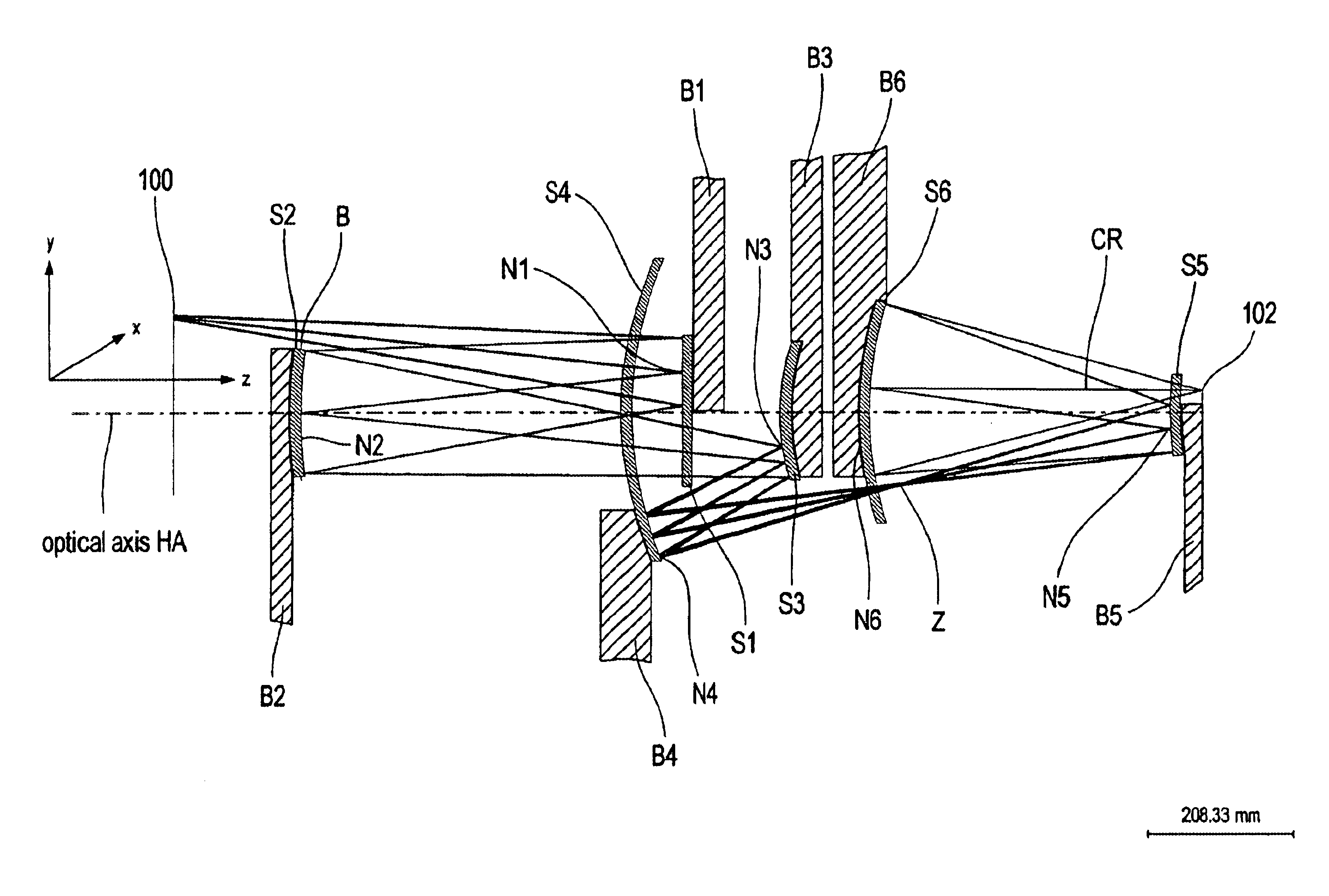
In addition, the example of embodiment 1 according to FIG. 4 involves a system with intermediate image Z. The intermediate image Z is formed geometrically after the first mirror S1 between the fourth and fifth mirrors S4, S5. The system according to FIG. 4 is divided into two subsystems by intermediate image Z: a first subsystem comprising mirrors S1, S2, S3, and S4, as well as a second subsystem comprising mirrors S5 and S6.

The volume claims B1 to B4 and B6 of mirrors S1 to S4 and S6 amount to at least 50 mm, and the volume claim B5 of the fifth mirror amounts to at least one-third of the diameter of the volume claim of the fifth mirror, so that a free working distance between the fifth mirror S5 next to the wafer and image plane 102 of at least 12 mm is guaranteed.

first embodiment

The Code V data of the first embodiment according to FIG. 4 are shown in Table 1 in FIG. 11. Here the element numbers 1, 2, 3, 4, 5, 6 designate mirrors S1, S2, S3, S4, S5 and S6.

The numerical aperture of the system on the image side according to example of embodiment 1 amounts to 0.25.

second embodiment

the invention is shown in FIG. 5. The components that are the same as in FIG. 4 are given the same reference numbers. Again, all six mirror surfaces are aspheric, but in contrast to the embodiment according to FIG. 4, the first mirror S1 is not convex, but rather concave.

The Code V data of the system are shown in Table 2 in FIG. 12. The numerical aperture of the projection objective according to FIG. 5 amounts to NA=0.25, as in the case of the first form of embodiment according to FIG. 4.

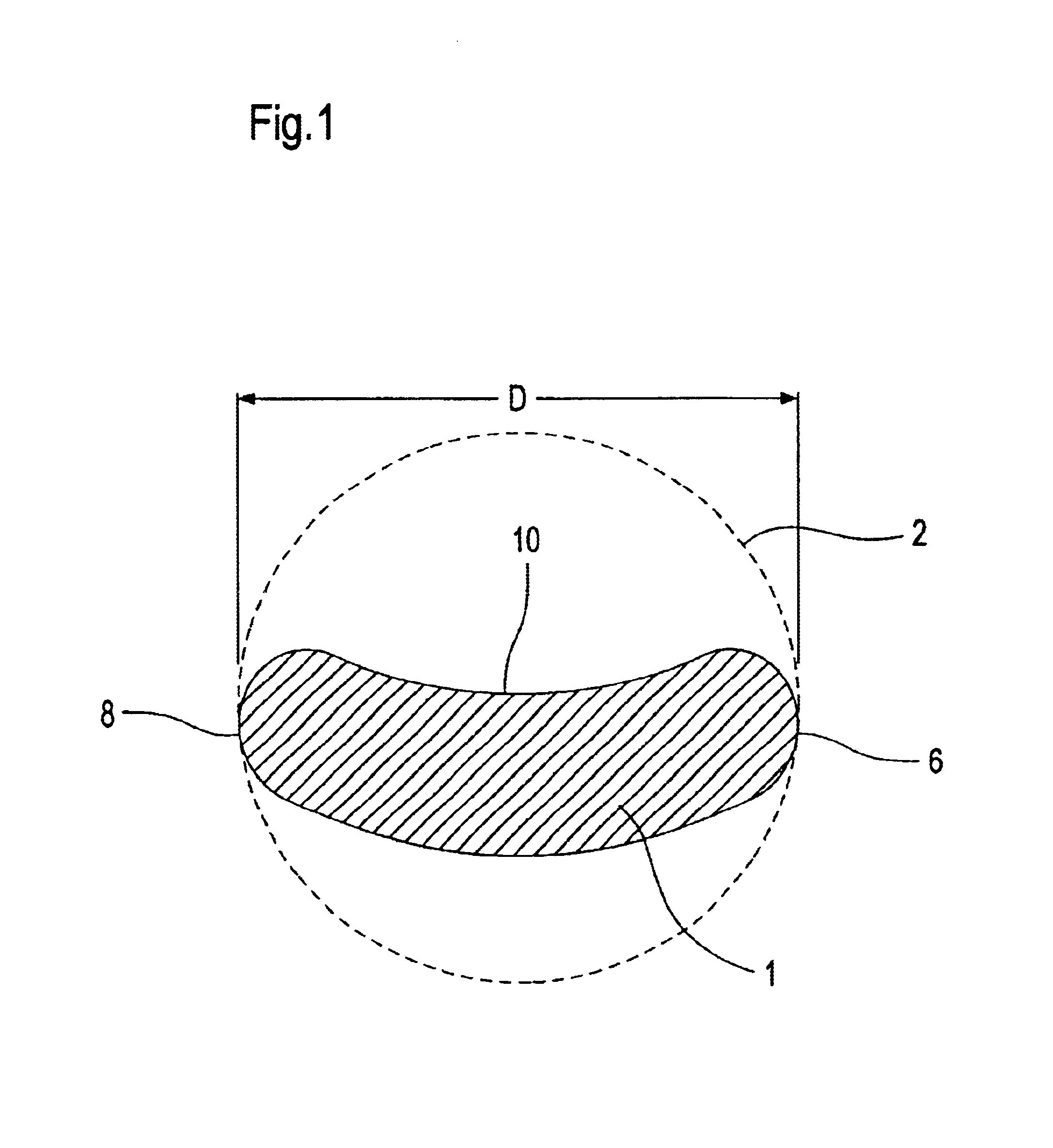
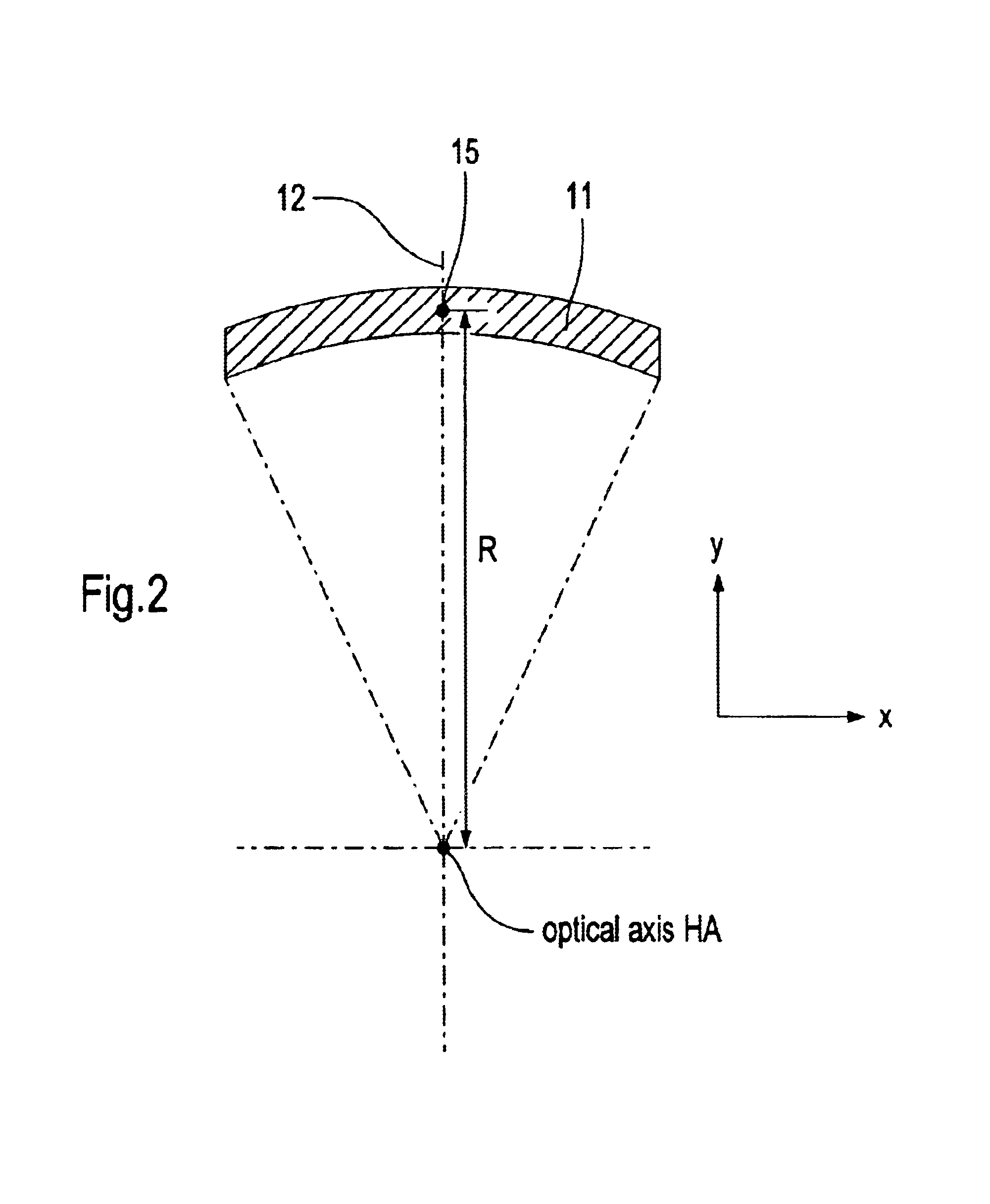
In the example of embodiment according to FIG. 5, according to the invention, the diameter D of the off-axis segments of all mirrors arranged in the objective are less than 300 mm, whereby the object to be imaged is the segment of a ring field, as shown in FIG. 2.

The off-axis segment in the x-y plane of the respective mirror of the second example of embodiment according to FIG. 5 is shown in FIGS. 6a to 6f. The x-y coordinate system as defined by the object plane is denoted in all illustrations. Her...


PUM

PropertyMeasurementUnit
diameteraaaaaaaaaa
diameteraaaaaaaaaa
angle of incidenceaaaaaaaaaa

Abstract

There is provided a microlithography projection objective for short wavelengths, with an entrance pupil and an exit pupil for imaging an object field in an image field, which represents a segment of a ring field, in which the segment has an axis of symmetry and an extension perpendicular to the axis of symmetry and the extension is at least 20 mm. The objective comprises a first (S1), a second (S2), a third (S3), a fourth (S4), a fifth (S5) and a sixth mirror (S6) in centered arrangement relative to an optical axis. Each of these mirrors have an off-axis segment, in which the light beams traveling through the projection objective impinge. The diameter of the off-axis segment of the first, second, third, fourth, fifth and sixth mirrors as a function of the numerical aperture NA of the objective at the exit pupil is ≦1200 mm * NA.

Description

BACKGROUND OF THE INVENTION1. Field of the InventionThe present invention relates to a microlithography objective and, more particularly, to a microlithography projection objective for short wavelengths, preferably ≦93 nm, a projection exposure system that includes such a microlithography projection objective, and a chip manufacturing process that employs such a projection exposure system.Lithography with wavelengths<193 nm, particularly EUV lithography with λ=11 nm or λ=13 nm is discussed as a possible technique for imaging of structures<130 nm, most preferably <100 nm. The resolution of a lithographic system is described by the following equation:RES=k1·λ / NA,wherein k1 denotes a specific parameter of the lithography process, λ denotes the wavelength of the incident light and NA is the numerical aperture of the system on the image side.Reflective systems with multilayers are used as optical components for imaging systems in the EUV range. Preferably Mo / Be systems are...

Claims


Application Information

Patent Timeline
Patent Type & Authority Patents(United States)
IPC IPC(8): G02B17/06G02B17/00G03F7/20
CPCG03F7/70233G02B17/0657
Inventor MANN, HANS-JURGENDINGER, UDOMUHLBEYER, MICHAEL
Owner CARL ZEISS SMT GMBH
Why Eureka
Try Eureka