

Use of drill bit energy for tomographic modeling of near surface layers
a technology of tomographic modeling and drill bit energy, which is applied in the direction of seismology for waterlogging, using reradiation, instruments, etc., can solve the problems of many wells for field development drilled at poor locations, distortion of the image of objective horizons, and unaccounted effects of these effects
- Summary
- Abstract
- Description
- Claims
- Application Information
AI Technical Summary
Benefits of technology
Problems solved by technology
Method used
Image

Examples
Embodiment Construction
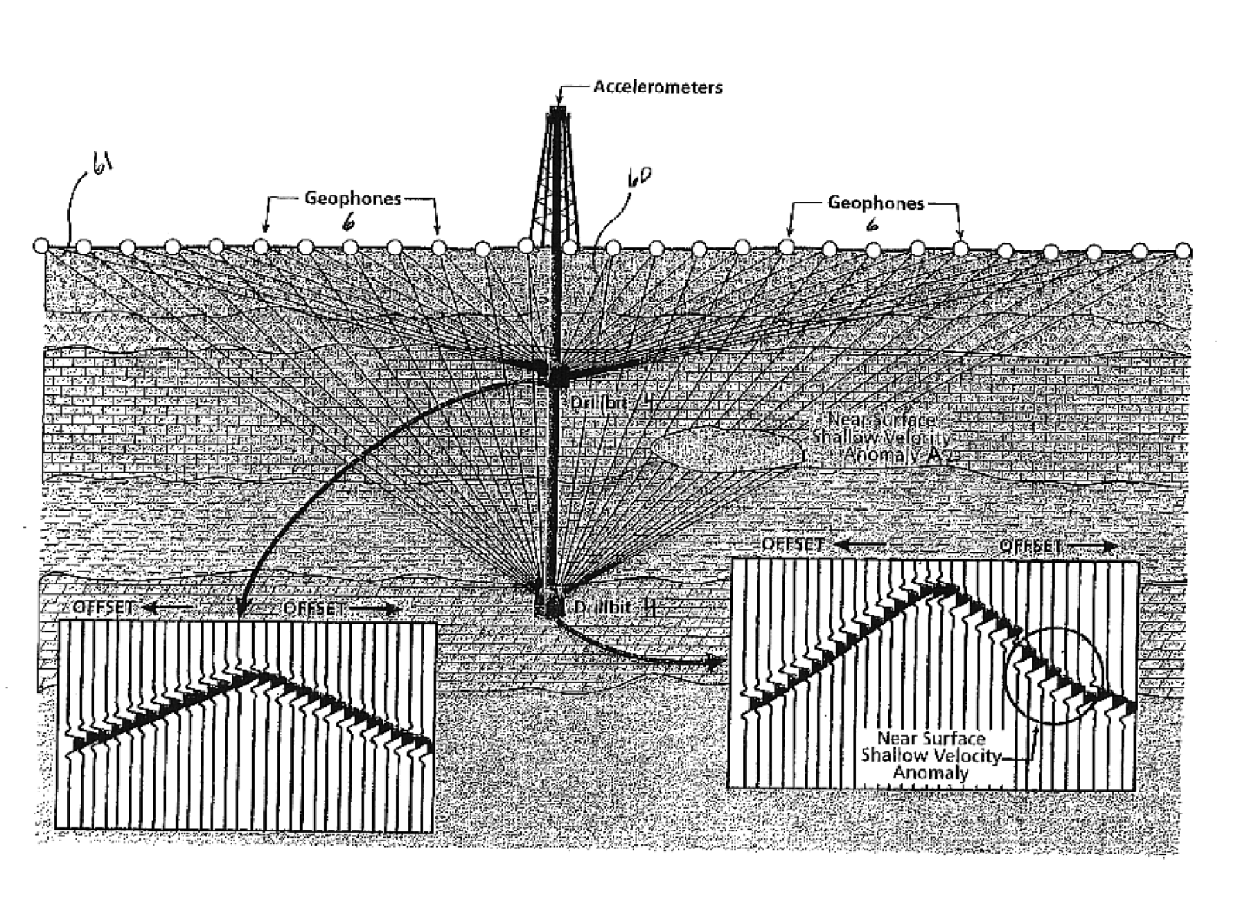
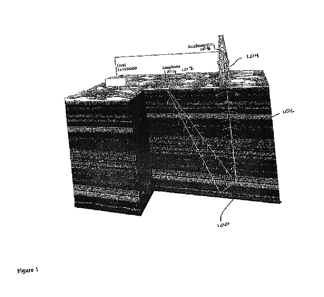
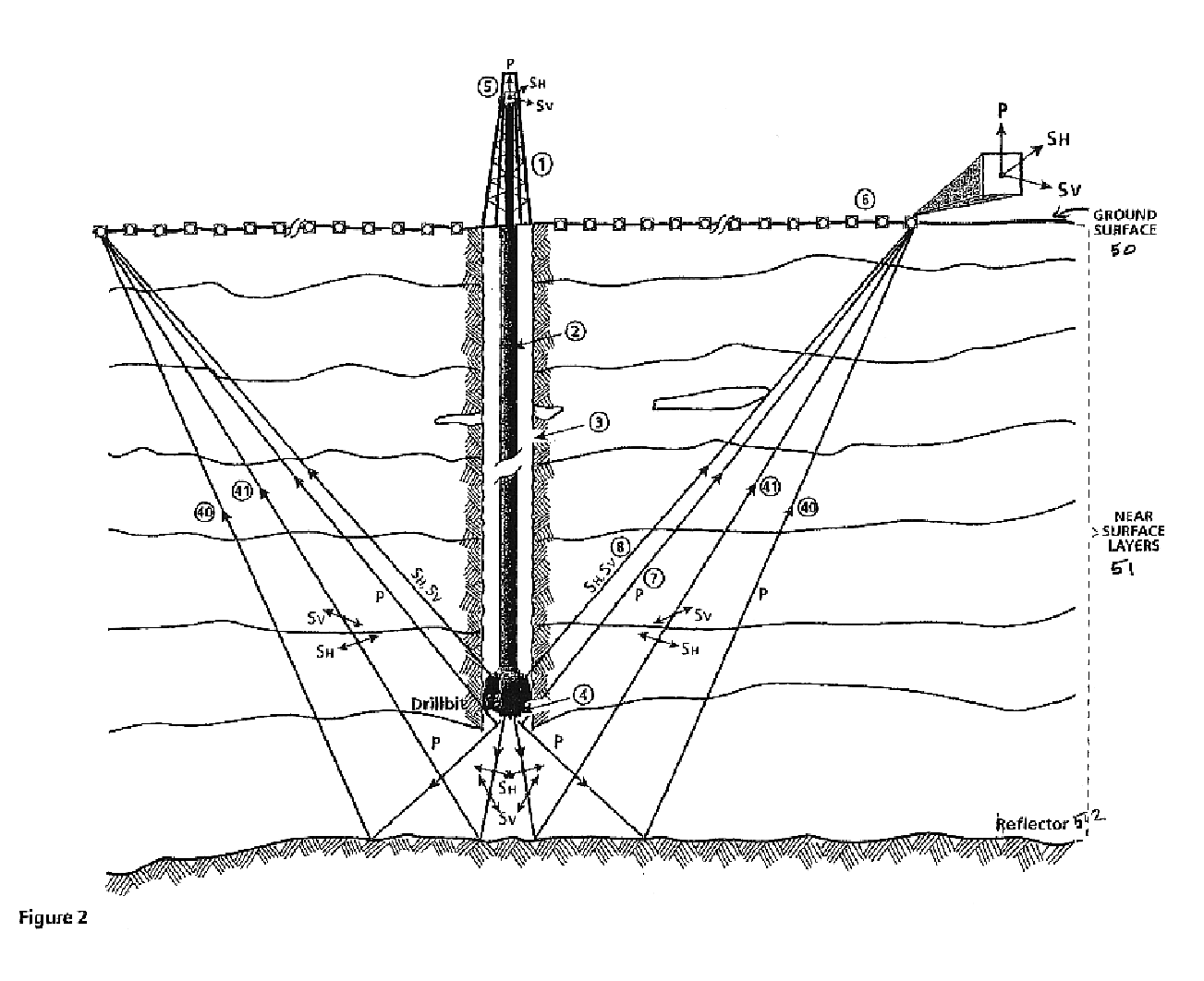
As described above, in SWD the drill bit, while drilling the rock formation, produces a seismic source at its deepest point by abrading and boring through the rocks and induces acoustic energy radially from the borehole and in all other directions. As the waves penetrate the shallow layers, the delay times for direct waves from the source to the receivers on the surface are detected. In addition, the waves reflected from rock layer interfaces below the drill bit are recorded on the same receivers. As the drilling progresses, each seismic data point is acquired from a source at a greater depth than before. The direct travel times to the formations encountered by the drill bit and the reflected times from formations below the drill bit are detected. The travel times of direct and reflected arrivals at each geophone location for various azimuths are recorded at closely spaced depth intervals for several wells drilled in an area.
These times are used in a joint tomographic travel-time in...
PUM
 Abstract
Description
Claims
Application Information