Wavelength division multiplexing optical transmission apparatus

a transmission apparatus and wavelength division technology, applied in multiplex communication, instruments, optical elements, etc., can solve the problem of not being able to cope with the fluctuation of the filter center wavelength that may occur

Inactive Publication Date: 2005-03-15
FUJITSU LTD
View PDF11 Cites 48 Cited by
  • Summary
  • Abstract
  • Description
  • Claims
  • Application Information

AI Technical Summary

Benefits of technology

[0011]In view of the above-described problem, it is an object of the present invention to provide a wavelength division multiplexing optical transmission apparatus wherein, in addition to the prior art technique that detects and controls the temperature of the AWG which indirectly indicates the filter characteristics of the AWG, means for directly monitoring fluctuations in filter wavelength is incorporated in the AWG to directly detect the filter wavelength fluctuations caused by the temperature characteristics and aging of the component parts, and the temperature of the AWG is controlled in such a manner as to cancel the effect of the fluctuation.

Problems solved by technology

However, since its component parts themselves are subject to initial variations and other characteristic degrading factors such as temperature variations and aging, the prior art temperature control circuit, 13 to 16, has had the problem that if the initial variations existing in the component parts can be accommodated at the time of initial setting, there is no way to cope with the fluctuation of the filter center wavelength that may occur due to temperature variations of the parts, aging of the AWG, etc. during operation thereafter.
As a result, the wavelength division multiplexing optical transmission apparatus has had to be designed by also considering wavelength stability degrading factors such as temperature characteristics and aging, and this has been one of the great barriers to the development of higher density wavelength division multiplexing optical transmission apparatus.

Method used


Image

  • Wavelength division multiplexing optical transmission apparatus
  • Wavelength division multiplexing optical transmission apparatus
  • Wavelength division multiplexing optical transmission apparatus

Examples


first embodiment

[0037]FIG. 4 is a diagram showing the present invention.

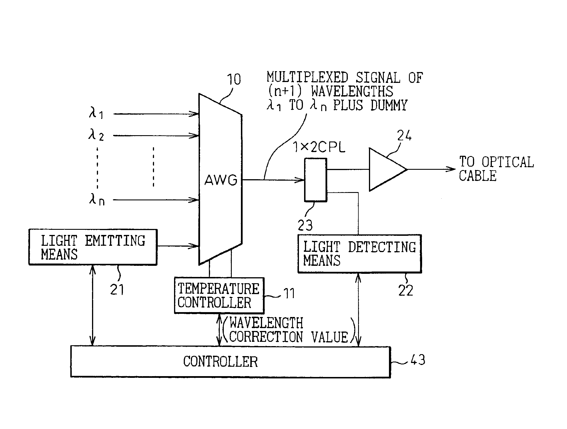
[0038]This embodiment shows an example in which the present invention is applied to the transmitting side of a wavelength division multiplexing optical transmission apparatus. In FIG. 4, one of the input ports on the AWG 10 which performs wavelength division multiplexing is preassigned for input of light of a wavelength different from any of the operating wavelengths λ1 to λn used for signal transmission to the receiving side (the preassigned input port is hereinafter designated the dummy port 20). A light emitting means 21 for generating the pilot signal is connected to the dummy port 20 of the AWG 10, so that a wavelength division multiplexed signal carrying a total of (n+1) waves, i.e., the operating wavelengths λ1 to λn plus the pilot signal, is output from the output port of the AWG 10.

[0039]The wavelength division multiplexed signal from the output port of the AWG 10 is split by a coupler (1×2 CPL) 23 into two outputs: on...

third embodiment

[0058]FIGS. 10 and 11 are diagrams showing the present invention.

[0059]As shown in FIG. 10, in this embodiment, a controller 43 constructed from a microprocessor circuit is used to control the temperature control circuit 11 for the AWG 10; here, for the control operation, the controller 43 uses the temperature control table 44 shown in FIG. 11. The temperature control table 44 stores reference voltage values for correcting for the amount of wavelength fluctuation detected by the light detecting means 22, and write values to a D / A converter (not shown) for generating the respective voltage values; the temperature control circuit 11 is controlled by the output of the D / A converter.

[0060]In this way, using the temperature control table 44 and the amount detected by the light detecting means 22, the controller 43 applies appropriate correction to the amount of fluctuation, such as in the filter characteristics of the AWG 10, in accordance with a program using a prescribed correction alg...


PUM

PropertyMeasurementUnit
wavelength multiplexedaaaaaaaaaa
temperatureaaaaaaaaaa
wavelengthsaaaaaaaaaa

Abstract

The present invention is directed to the provision of a wavelength division multiplexing optical transmission apparatus and, more particularly, to a wavelength division multiplexing optical transmission apparatus having high wavelength stability unaffected by the temperature characteristics, aging, etc. of an arrayed-waveguide grating (AWG) and its peripheral components. The wavelength division multiplexing optical transmission apparatus comprises: an arrayed-waveguide grating 10 having operating input/output ports and an input dummy port; a light emitting means 21 for generating a pilot signal to be input to the input dummy port; a light detecting means 22 for monitoring the pilot signal contained in a wavelength division multiplexed signal output from the operating output port; and a temperature control circuit 11 for controlling the temperature of the arrayed-waveguide grating in such a manner as to cancel the amount of wavelength fluctuation occurring in the arrayed-waveguide grating and detected by monitoring the pilot signal.

Description

BACKGROUND OF THE INVENTION[0002]1. Field of the Invention[0003]The present invention relates to an optical transmission apparatus. More particularly, the invention relates to a wavelength division multiplexing optical transmission apparatus that uses wavelength division multiplexing (WDM) for transmitting large amounts of data at high speed through a single optical fiber by multiplexing / demultiplexing optical signals of different wavelengths, and specifically to a wavelength division multiplexing apparatus in which the stability and accuracy of a filter bandwidth for each signal is increased for higher density wavelength multiplexing.[0004]2. Description of the Related Art[0005]FIGS. 1A to 3 are diagrams showing one configuration example of a multiplexer / demultiplexer in a prior art wavelength division multiplexing optical transmission apparatus.[0006]The example shown in FIG. 1A uses an arrayed-waveguide grating (AWG) 10, the dominant type of optical multiplexer / demultiplexer in u...

Claims


Application Information

Patent Timeline
Patent Type & Authority Patents(United States)
IPC IPC(8): G02B6/34H04J14/02G02B6/12G02F1/01H04B10/07H04B10/293H04B10/564H04B10/572H04J14/00
CPCH04J14/02G02B6/12026
Inventor KIMOTSUKI, KOICHIHAYAMI, KAZUNORINAGAYOSHI, TATSUOMAKI, TAKANORI
Owner FUJITSU LTD
Why Eureka
Try Eureka