
Method and apparatus for optimizing skip mask operations in a disc drive

a disc drive and skip mask technology, applied in the direction of maintaining head carrier alignment, recording information storage, instruments, etc., can solve the problems of large time, latency delay, and non-linear relationship, and achieve the effect of increasing the performance of the disc driv

Inactive Publication Date: 2005-03-15
SEAGATE TECH LLC
View PDF3 Cites 20 Cited by
  • Summary
  • Abstract
  • Description
  • Claims
  • Application Information

AI Technical Summary

Benefits of technology

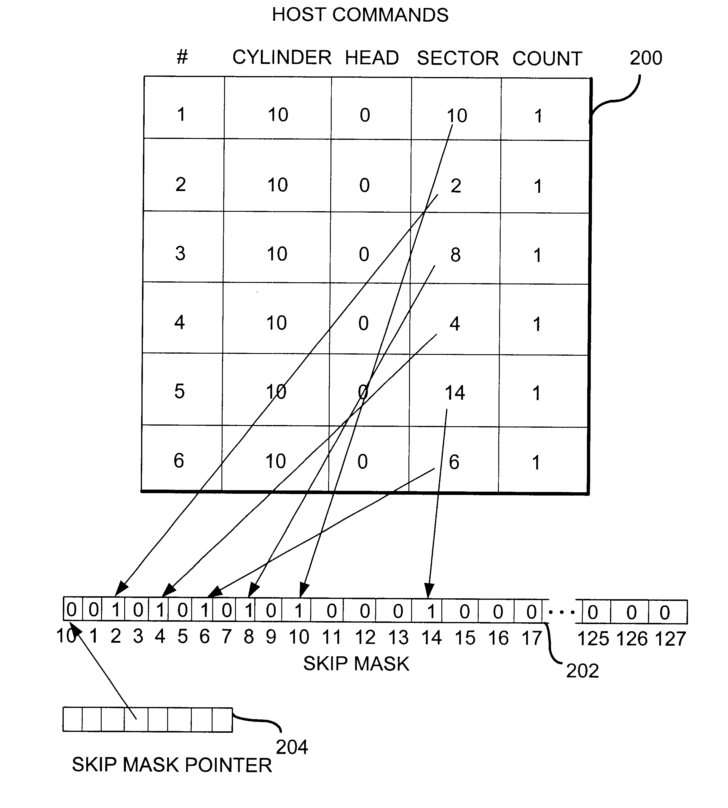
Against this backdrop the present invention has been developed. The present invention is essentially an implementation of a skip mask scheme which reduces the number of necessary disc rotations of a disc during pseudo-sequential accesses. That is, it increases the performance of a disc drive during accesses of read and write commands that land on the same track but are not sequential and / or contiguous by minimizing the number of necessary disc rotations.

Problems solved by technology

Generally, the amount of time to switch between two tracks depends on the distance between the tracks; however, the relationship is not linear due to a certain amount of overhead involved in track switching.
This causes a latency delay since the servo system must wait for the correct sector to arrive under the head.
In a computing system, a millisecond is an enormous amount of time when the system memory speed is measured in nanoseconds.
On the other hand, latency is an important performance-limiting factor for reading or writing noncontiguous multiple data blocks on a track.
Every sector in a disc drive is a good sector in an ideal world; however, typical disc drives contain unusable sectors when they are manufactured, because it is virtually impossible to create a disc drive with several million sectors and not have some errors.
Imperfections in the media coating on the disc or other problems, for example, may make a sector inoperable.
This usually shows up as an error when attempting to read the sector.
Modern disc drives use an error correction code to help identify when errors occur and in some cases to correct them; however, there will still be physical flaws that prevent parts of a disc from being used.
These unusable sectors, due to such physical flaws, are called defective sectors.
Nevertheless, a seek time delay cannot be avoided if more defective sectors are present on the track than available spare sectors on that track.
Moreover, in most cases, mapping a defective sector to a spare sector causes fragmentation of data.
Once data is fragmented, each fragment of data introduces a latency delay to locate the beginning sector of each fragment and, if the next fragment starts on a different track, an additional seek time delay is introduced.
Thus, there is a big performance difference between accessing data that is laid out contiguously on a disc and accessing data that is fragmented into a dozen pieces.
In any case, greater seek time and / or latency causes slower access to data stored in a disc drive.
However, during typical operation, commands are rarely sent which access data in large sequential, contiguous blocks.
In this case, latency becomes a significant performance-reducing factor because even though all sectors may be located on the same track (thus seek time not being a performance issue), they are not in order, or may have rotated beyond head during the current disc rotation.
In a disc drive, errors are sometimes encountered during the transfer of data.
This mechanism will complicate the error recovery scheme, and will necessitate an enhanced buffer management technique to compensate.

Method used


Image

  • Method and apparatus for optimizing skip mask operations in a disc drive
  • Method and apparatus for optimizing skip mask operations in a disc drive
  • Method and apparatus for optimizing skip mask operations in a disc drive

Examples


Embodiment Construction

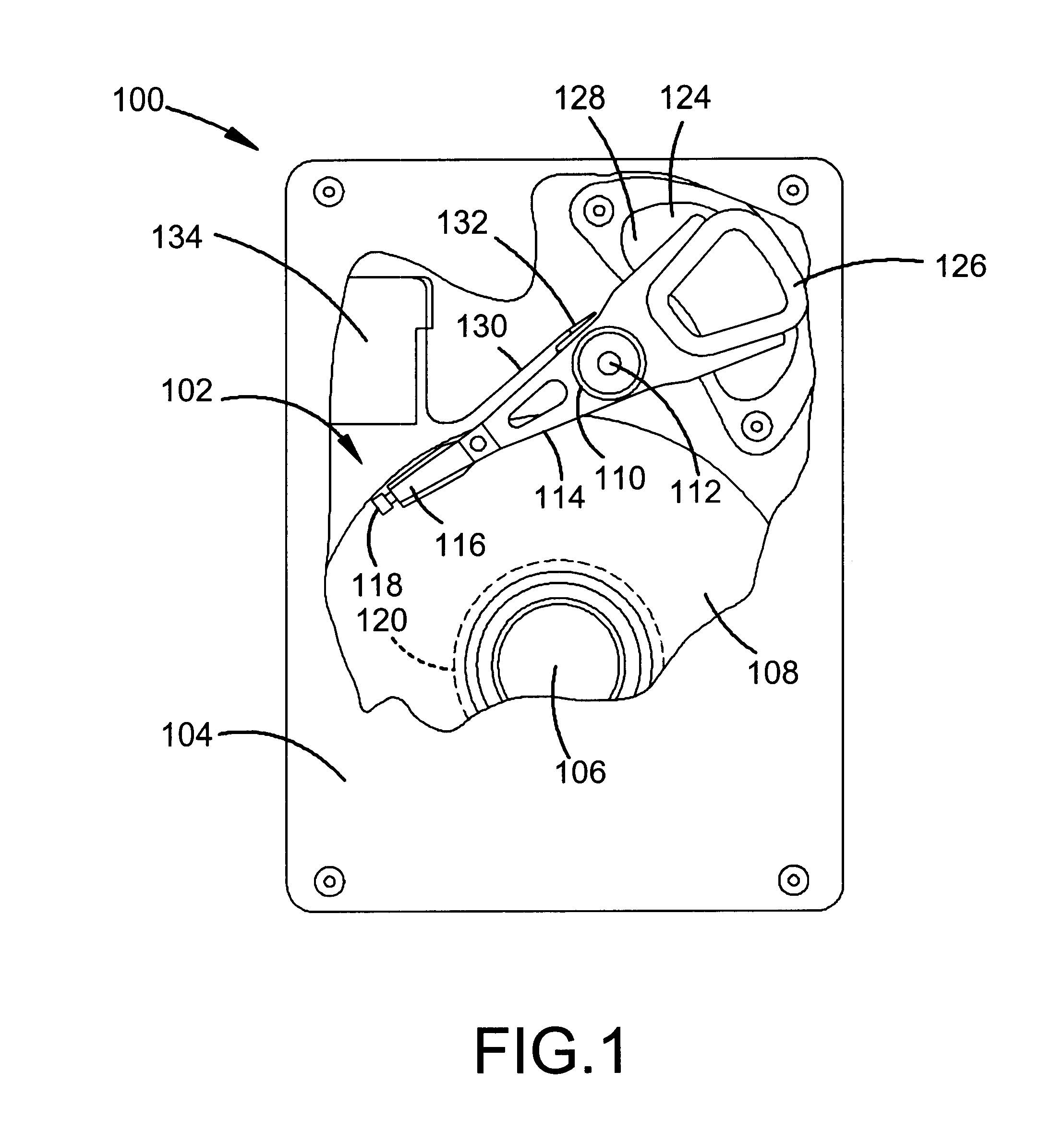
A disc drive 100 constructed in accordance with a preferred embodiment of the present invention is shown in FIG. 1. The disc drive 100 includes a base 102 to which various components of the disc drive 100 are mounted. A top cover 104, shown partially cut away, cooperates with the base 102 to form an internal, sealed environment for the disc drive in a conventional manner. The components include a spindle motor 106 which rotates one or more discs 108 at a constant high speed. Information is written to and read from tracks on the discs 108 through the use of an actuator assembly 110, which rotates during a seek operation about a bearing shaft assembly 112 positioned adjacent the discs 108. The actuator assembly 110 includes a plurality of actuator arms 114 which extend towards the discs 108, with one or more flexures 116 extending from each of the actuator arms 114. Mounted at the distal end of each of the flexures 116 is a head 118 which includes an air bearing slider enabling the he...


PUM

PropertyMeasurementUnit
current bitaaaaaaaaaa
speedaaaaaaaaaa
seek timeaaaaaaaaaa

Abstract

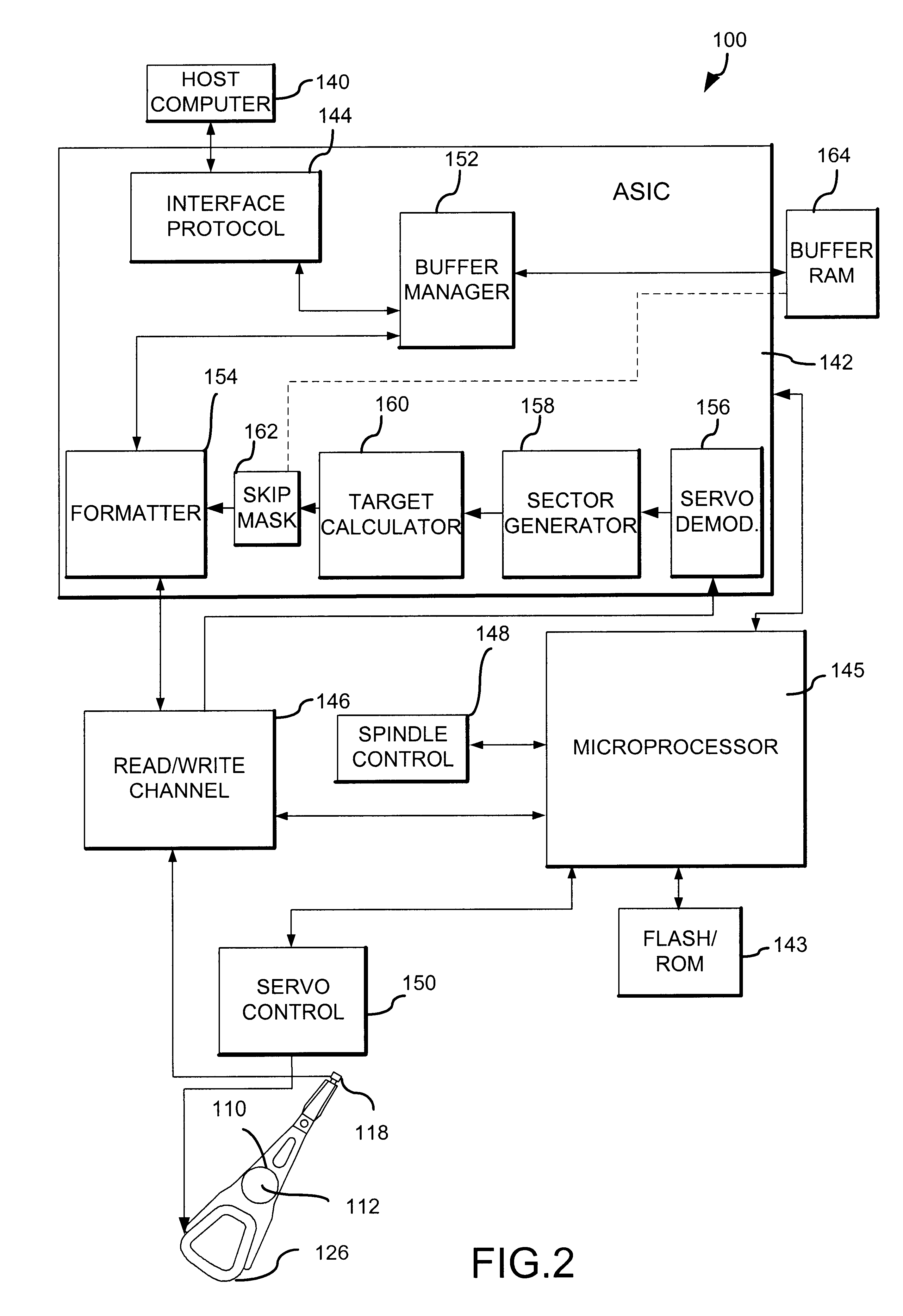
A skip mask mechanism is implemented in a disc drive in order to increase performance by minimizing the number of necessary disc rotations required while executing a set of pseudo-sequential commands. The drive includes an interface between the host computer and the drive, a read / write channel between the interface and the transducer / head, a formatter between the interface and the read / write channel for timing when data is transferred between the interface and the read / write channel, and a skip mask mechanism interposed between a target calculator and the formatter that provides a masked input to the formatter for controlling passage of data between the interface and the read / write channel.

Description

FIELD OF THE INVENTIONThis application relates generally to data storage management in a disc drive having logically non-consecutive sectors, and more particularly to an implementation of skip mask hardware to assist in minimizing the number of necessary disc rotations in accessing a set of logically non-consecutive sectors.BACKGROUND OF THE INVENTIONDisc drives are data storage devices that store digital data in magnetic form on a rotating storage medium called a disc. Modern disc drives comprise one or more rigid discs that are coated with a magnetizable medium and mounted on the hub of a spindle motor for rotation at a constant high speed. Each surface of a disc is divided into several thousand tracks that are tightly-packed concentric circles similar in layout to the annual growth rings of a tree. The tracks are typically numbered starting from zero at the track located outermost the disc and increasing for tracks located closer to the center of the disc. Each track is further b...

Claims


Application Information

Patent Timeline
Patent Type & Authority Patents(United States)
IPC IPC(8): G11B5/55
CPCG11B5/5521
Inventor HOSKINS, EDWARD SEANSEUBERLING, FRANCIS T.
Owner SEAGATE TECH LLC
Learn More