Position sensing with improved linearity

Inactive Publication Date: 2005-03-22
ANALOG DEVICES IMI
View PDF63 Cites 105 Cited by
  • Summary
  • Abstract
  • Description
  • Claims
  • Application Information

AI Technical Summary

Benefits of technology

The invention, roughly described, comprises a position-sense interface with improved transfer characteristics. In one embodiment of the invention, a single proof-mass includes two electrically decoupled sensing capacitors is shown. Electrical position detection circuitry, which may be substantially time-multiplexed

Problems solved by technology

Note force-feedback is not practical or even desirable for many applications, however.
As full scale ranges rise above approximately 50G, it becomes increasingly difficult to force balance an accelerometer in a manner such that the feedback loop doesn't saturate, especially if electrostatic forces and low-voltage operation (i.e. 5V or less) are used to apply the restoring f

Method used


Image

  • Position sensing with improved linearity
  • Position sensing with improved linearity
  • Position sensing with improved linearity

Examples


first embodiment

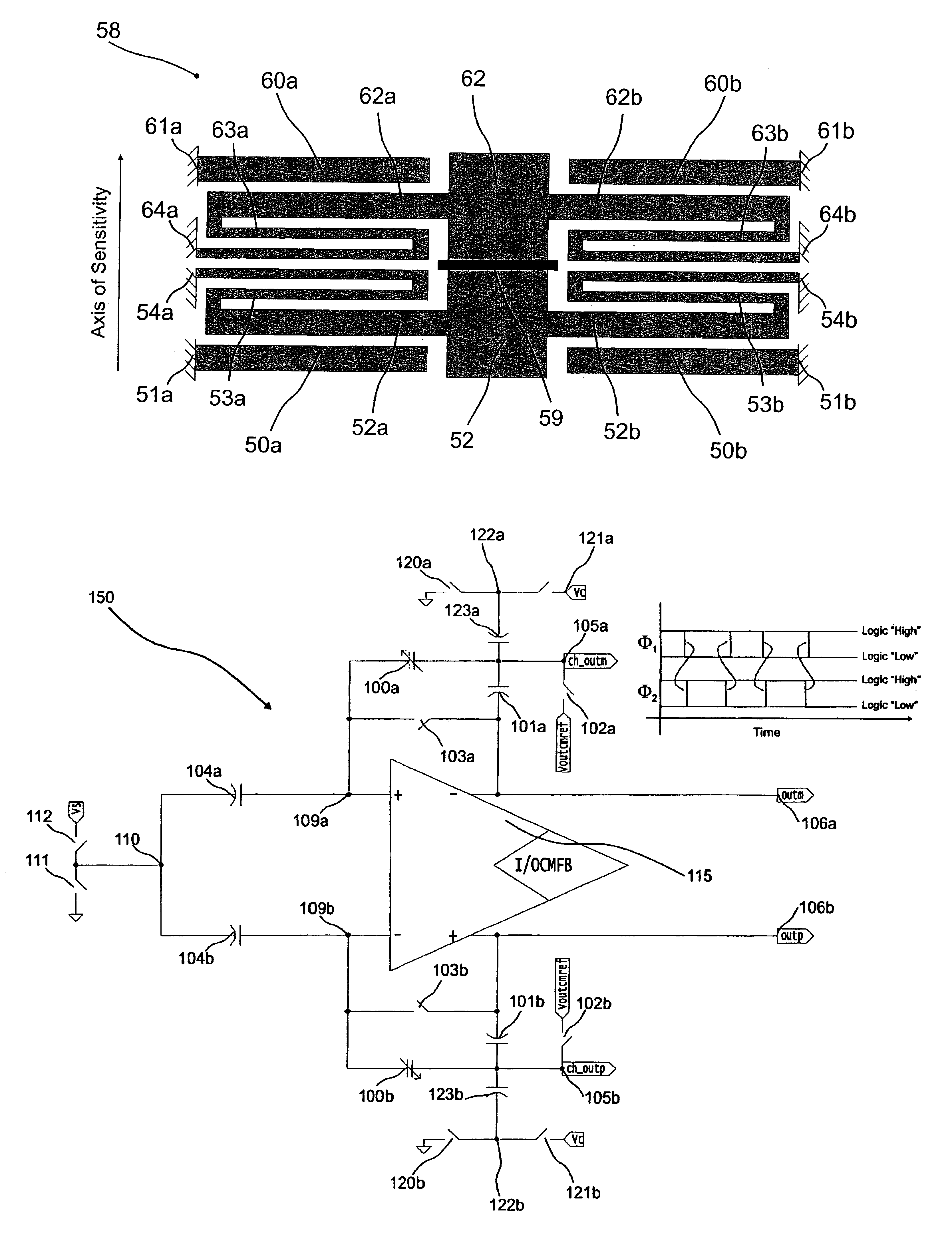
the present invention is schematically illustrated in FIG. 6. In this embodiment, position sense interface 150 comprises a differential opamp 115 having an ISODCMFB circuit and a negative feedback loop, the feedback loop operating in a sampled-data, i.e. time-multiplexed, fashion. Position sense interface 150 further comprises sense capacitors 100a,b each having a nominal sense capacitance Cs, reference capacitors 104a,b each having a capacitance of Cref, feedback coupling capacitors 101a,b, feedforward capacitors 123a,b, output terminals 105a,b, opamp output terminals 106a,b, unity-feedback switches 103a,b, output zeroing switches 102a,b, and feedforward compensation switches 120a,b and 121a,b. Switches may be formed using, for example a NMOS transistor, a PMOS transistor, or both a NMOS and a PMOS transistor.

Position sense interface 150 operates over two recurring, discrete, nonoverlapping time periods Phi1 (Φ1) and Phi2 (Φ2). Typical period frequencies are between 1 kHz and 10 MH...

third embodiment

the present invention is shown in FIG. 10. Position sense interface 350 operates in the continuous-time, or frequency multiplexed, domain. Opamp 315 may be similar to opamp 199 described in the first embodiment, and includes an ISODCMFB circuit. A modulation signal, which may be a sinusoid or a square wave for example, is applied to input terminal 310. Typical frequencies are between 1 kHz and 10 MHz with a magnitude from 0.1 to 5V. Resistors 303a,b are large valued and set the low-frequency voltage at the input terminals 309a,b while minimally affecting the response of the position-sense interface at frequencies close to the modulation frequency. Resistors 303a,b may be formed by a MOS transistor operating in subthreshold regime, for example. Likewise, resistors 302a,b set the low-frequency voltage at the output terminals 305a,b. The position-sense signal is reconstructed by demodulating the differential output voltage from output terminals 305a,b via a demodulator such as a synchr...

fourth embodiment

the present invention is shown in FIG. 11. Position sense interface 450 operates in the continuous-time domain. Opamp 415 may be similar to opamp 199 described in the first embodiment, and includes an ISODCMFB circuit. A modulation signal, which may be a sinusoid or a square wave for example, is applied to input terminal 410. Typical frequencies are between 1 kHz and 10 MHz with a magnitude from 0.1 to 5V. Resistors 403a,b are large valued and set the low-frequency voltage at the input terminals 409a,b while minimally affecting the response of the position-sense interface at frequencies close to the modulation frequency. The position-sense signal is reconstructed by demodulating the differential output voltage from output terminals 406a,b via a demodulator such as a synchronous demodulator synchronized to the voltage at node 410.

The present invention further provides for application of a force quasi-constant over displacement, but with a controlled variation over time. In the contex...


PUM


Abstract

A position-sense interface with improved transfer characteristics. Electrical position detection circuitry, which may be substantially time-multiplexed or frequency-multiplexed, comprises a differential charge integrator with input-sensed output-driven common mode feedback. By placing sense capacitors in the feedback loop of said differential charge integrator with input-sensed output-driven common mode feedback, improved position sensing linearity is attained. In some embodiments of the invention, a compensating charge is applied to the sense capacitors in a fashion that minimizes the output common mode shift of the opamp. The magnitude of the compensating charge may be preset at a substantially constant level, or derived by a feedback loop that measures the shift in output common mode voltage in response to an excitation signal and adjusts the magnitude of the compensating charge to drive said shift towards zero.
The invention has numerous advantages for acceleration measurement in both open-loop and force-balanced accelerometers, as well as rotation rate measurement in a vibratory rate gyroscope. Other applications in which the invention may prove advantageous include: motion detection for an oscillation-sustaining feedback loop; position detection of actuators, including micro-actuators used for effecting controlled motion of a disk-drive read/write head, or effecting controlled motion of an optically active device, such as a positionable mirror for use in fiber-optic data communications; and application of electrostatic forces for large motions.

Description

BRIEF DESCRIPTION OF THE INVENTIONThis invention relates to an improved measuring device for open-loop and force-balanced accelerometers, and vibratory rate gyroscopes. In addition, the invention further relates to: position or velocity detection in an oscillation-sustaining feedback loop; position detection of actuators, including micro-actuators used for effecting controlled motion of a disk-drive read / write head, or effecting controlled motion of an optically active device, such as a positionable mirror used in data communications. The invention further relates to microelectromechanical systems formed by one or more micromachining operations.This invention utilizes charge-based sensing to attain a linear position-input to voltage-output transfer characteristic.BACKGROUND OF THE INVENTIONAccelerometers are sensors that measure acceleration. Accelerometers can be designed to measure rotational or translational acceleration. Vibratory rate gyroscopes are a type of accelerometer in w...

Claims


Application Information

Patent Timeline
IPC IPC(8): G01P15/125
CPCG01P15/125G01P2015/0814
Inventor LEMKIN, MARK A.JUNEAU, THOR N.CLARK, WILLIAM A.ROESSIG, ALLEN W.
Owner ANALOG DEVICES IMI
Why Eureka
Try Eureka