
Sub-atmospheric pressure delivery of liquids, solids and low vapor pressure gases

a technology of liquids and solids, applied in the direction of combustion-air/fuel-air treatment, steam generation using steam absorption, drying machines with progressive movements, etc., can solve the problems of insufficient use of venturi to sufficiently reduce the pressure in the system, reduce the pressure in the connecting line, and reduce the inherent problems

Inactive Publication Date: 2005-03-22
ENTEGRIS INC
View PDF14 Cites 52 Cited by
  • Summary
  • Abstract
  • Description
  • Claims
  • Application Information

AI Technical Summary

Benefits of technology

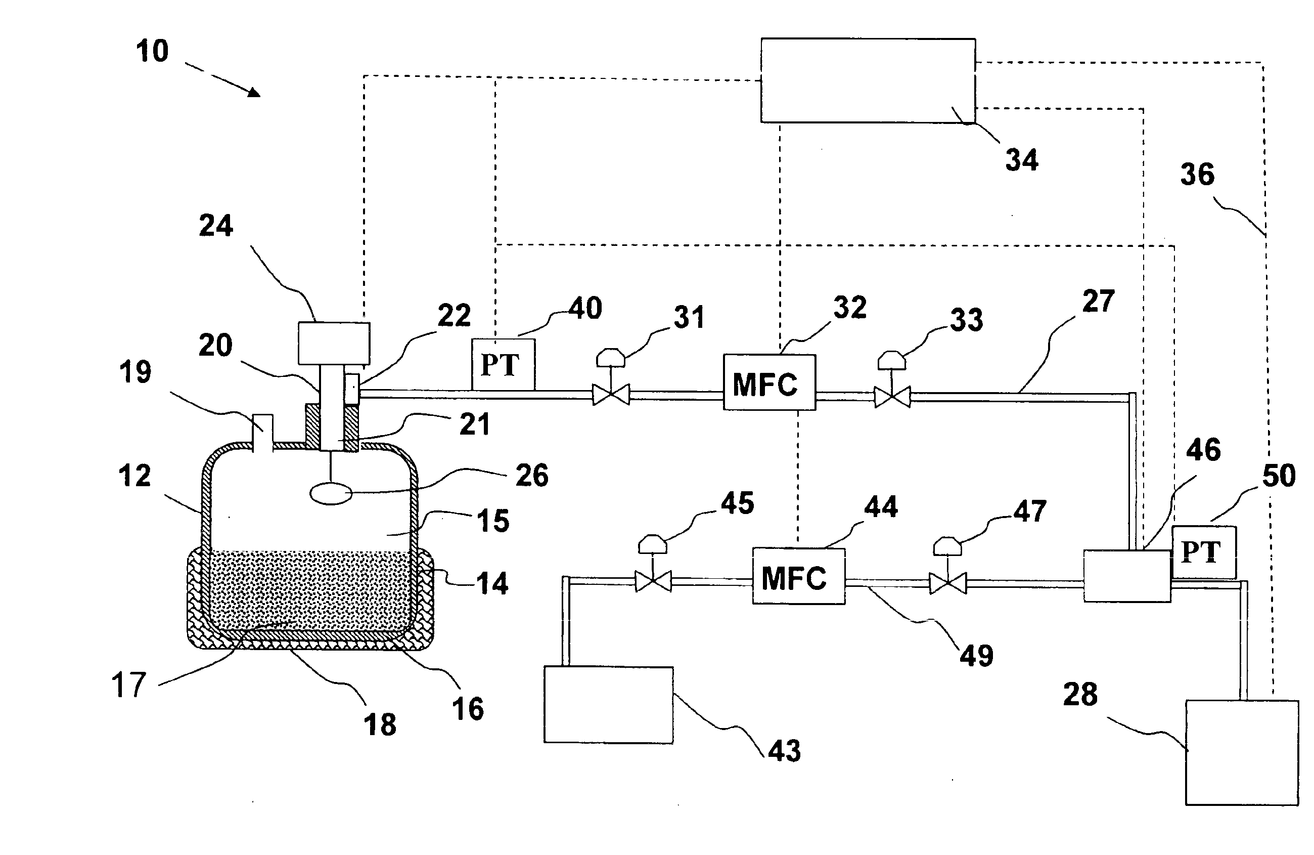
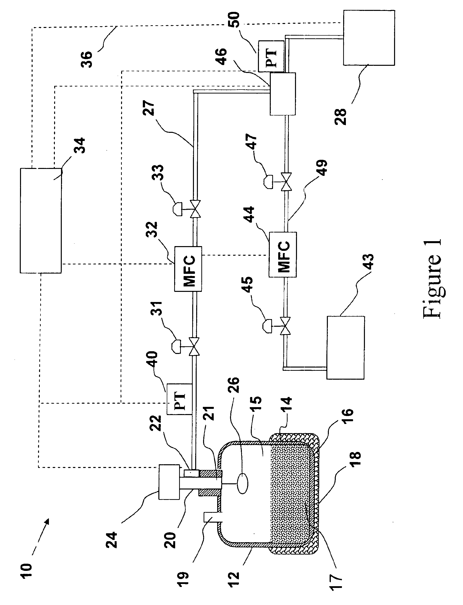
The processing tool may function at a lower sub-atmospheric pressure than that set in the gas pressure regulator thereby causing the gas pressure regulator to switch on and permit the vaporized source material to flow from the vaporization vessel. In the alternative, if the pressure is higher in the processing tool, the use of a venturi will act as a vacuum generator to provide sufficiently low pressure to actuate the pressure regulator within the vaporizer vessel thereby releasing the vaporized source material. Still further, in some conditions the use of a venturi may not be adequate to sufficiently reduce the pressure in the system and the use of vacuum pump, preferably a turbo pump connected via a manifold to a storage vessel, may be utilized to reduce the pressure in the connecting line. In all the alternative ways, the present invention eliminates the need for introducing a carrier gas directly into the vaporization vessel thereby reducing the inherent problems of tunneling within the bulk material.

Problems solved by technology

Still further, in some conditions the use of a venturi may not be adequate to sufficiently reduce the pressure in the system and the use of vacuum pump, preferably a turbo pump connected via a manifold to a storage vessel, may be utilized to reduce the pressure in the connecting line.

Method used


Image

  • Sub-atmospheric pressure delivery of liquids, solids and low vapor pressure gases
  • Sub-atmospheric pressure delivery of liquids, solids and low vapor pressure gases
  • Sub-atmospheric pressure delivery of liquids, solids and low vapor pressure gases

Examples


Embodiment Construction

The present invention is based on the discovery that delivery of a vaporized source material to a processing tool is optimized by flowing the vaporized source material between the vaporization vessel and the processing tool through a pressure differential, wherein the pressure of the vaporized source material leaving the vaporization vessel is at a higher subatmospheric pressure value than that downstream of the vaporization vessel. If the pressure differential is sufficient the need for a carrier gas and / or trace heating connecting flow lines may be eliminated. Further, the delivery system of the present invention, operating at sub-atmospheric pressures, introduces additional safety and control advantages. As the system is operated under a vacuum, releases—should they occur—are contained within the delivery system, and as such, exposure to workers from such incidents related to loss of integrity of the flow circuit system is almost non-existent. Additionally, it is not necessary to...


PUM

PropertyMeasurementUnit
pressureaaaaaaaaaa
pressureaaaaaaaaaa
threshold vapor pressureaaaaaaaaaa

Abstract

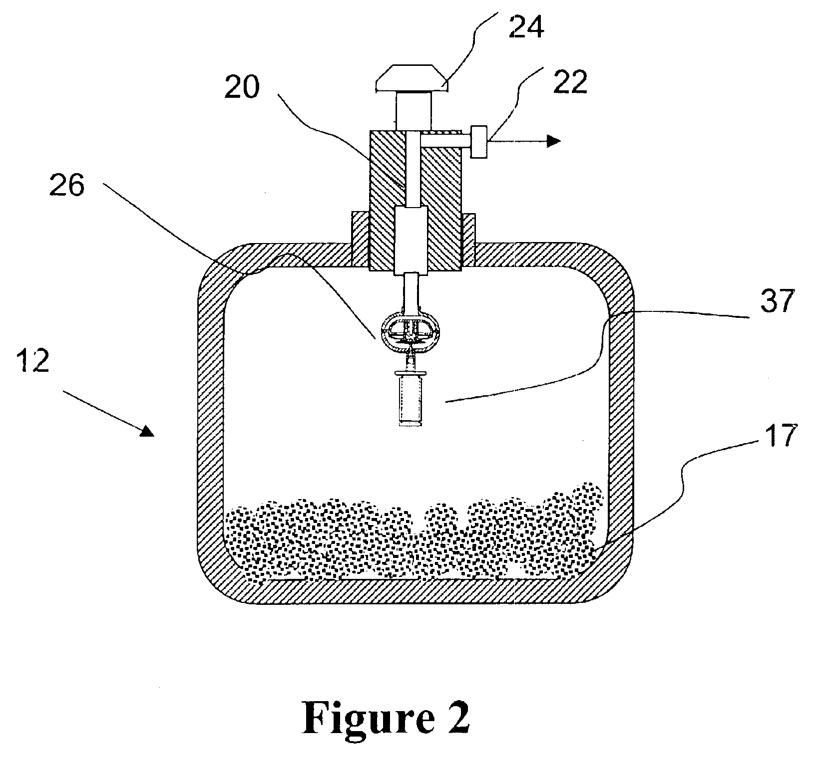
A delivery system and method for vaporizing and delivery of vaporized solid and liquid precursor materials at sub-atmospheric pressures between a heatable vaporization vessel and a processing tool. The system includes a pressure regulator internally positioned within the vaporization vessel and in fluid communication with a downstream mass flow controller to maintain a consistent flow of vaporized source material. The system further comprises introducing a carrier / diluent gas for diluting the vaporized source material before entry into the processing tool. A venturi is positioned directly upstream of the processing tool and provides for mixing of the carrier gas with the vaporized source material while providing the negative pressure required to open the gas pressure regulator within the vaporization vessel.

Description

BACKGROUND OF INVENTION1. Field of the InventionThe present invention relates to a vapor delivery system and method of use, and more particularly, to a delivery system for vaporized liquids, solids or low vapor pressure gases at sub-atmospheric pressures for use in metalorganic chemical vapor deposition (MOCVD) and chemical vapor deposition (CVD) processes.2. Description of the Related ArtMOCVD and CVD have been extensively used for preparation of films and coatings in semiconductor wafer processing. These deposition processes are favored because of their ability to provide highly conformal and high quality films, at relatively fast processing times. Further, these deposition processes are beneficial in coating substrates of irregular shapes including the provision of highly conformal films even with respect to deep contacts and other openings.In general, CVD techniques involve the delivery of vapor phase reactants to the surface of a substrate where chemical reactions take place un...

Claims


Application Information

Patent Timeline
Patent Type & Authority Patents(United States)
IPC IPC(8): C23C16/52C23C16/448H01L21/00
CPCC23C16/4481C23C16/52H01L21/67017F17C2205/0391F17C2205/0338Y10T137/87587
Inventor OLANDER, W. KARL
Owner ENTEGRIS INC
Learn More