Pail vent and method

a technology of vents and nozzles, applied in the direction of rigid containers, tubular containers, transportation and packaging, etc., can solve the problems of affecting the flow speed of the container, and entail an objectionable added cost factor, so as to achieve the effect of reducing the unit cost of the container, facilitating the flow of air, and ensuring the flow speed

Inactive Publication Date: 2005-03-22
AMERICAN FLANGE & MFG CO INC
View PDF9 Cites 4 Cited by
  • Summary
  • Abstract
  • Description
  • Claims
  • Application Information

AI Technical Summary

Benefits of technology

This invention offers a practical solution to the above mentioned prior art problem of attaining optimum pouring speed and smoothness of flow without permitting the entry of contaminants into the pail and at the same time without increasing the unit cost of the container. This is accomplished by a very minor modification of an already existing pail lid and dispensing closure construction. Most commonly pails or buckets in the five gallon range and particularly such containers molded of plastic resins are outfitted with a flexible pouring spout affixed to the lid opening and provided with a recloseable screw cap. Underneath the screw cap in the initial unopened state there is an integrally molded frangible sealing diaphragm closing off the spout opening which, prior to pouring, is easily torn out with an integrally connected ring pull member. This torn out closure component is normally just discarded or more likely becomes a piece of litter. In the invention construction and method this litter serves a very useful purpose. A puncture zone is formed in the pail lid diametrically opposite the dispensing closure surrounded by a retaining collar dimensioned to provide a snap fit upon insertion of the torn out sealing diaphragm. Thus it can be seen that in initially readying the pail for pouring, the puncture zone is penetrated with a screw drive or similar implement creating an air entry passage. The screw cap is removed after extending the spout and the spout sealing diaphragm torn out. After dispensing a desired quantity in a smooth surge free fashion, the torn sealing diaphragm is simply snapped into the retaining collar thus closing off the punctured opening and protecting against the unwanted entry of collected water or foreign matter.

Problems solved by technology

However, an open aperture in the pail top invites the entry of surface contaminants and is generally unacceptable.
This works very nicely but entails an objectionable added cost factor.
Numerous more expensive self venting pouring spouts have entered the market which to a certain degree lessen the additional manufacturing cost by eliminating the added labor component but fall far short in pouring performance from that resulting from the simple remotely positioned puncture vent.
To date, however, attempts in this direction have lacked practicality of molding in plastic lids in addition to including an undesirably complex puncturing step.
Most importantly the desired effective reclosing of the vent opening has remained elusive.

Method used


Image

  • Pail vent and method
  • Pail vent and method
  • Pail vent and method

Examples


Embodiment Construction

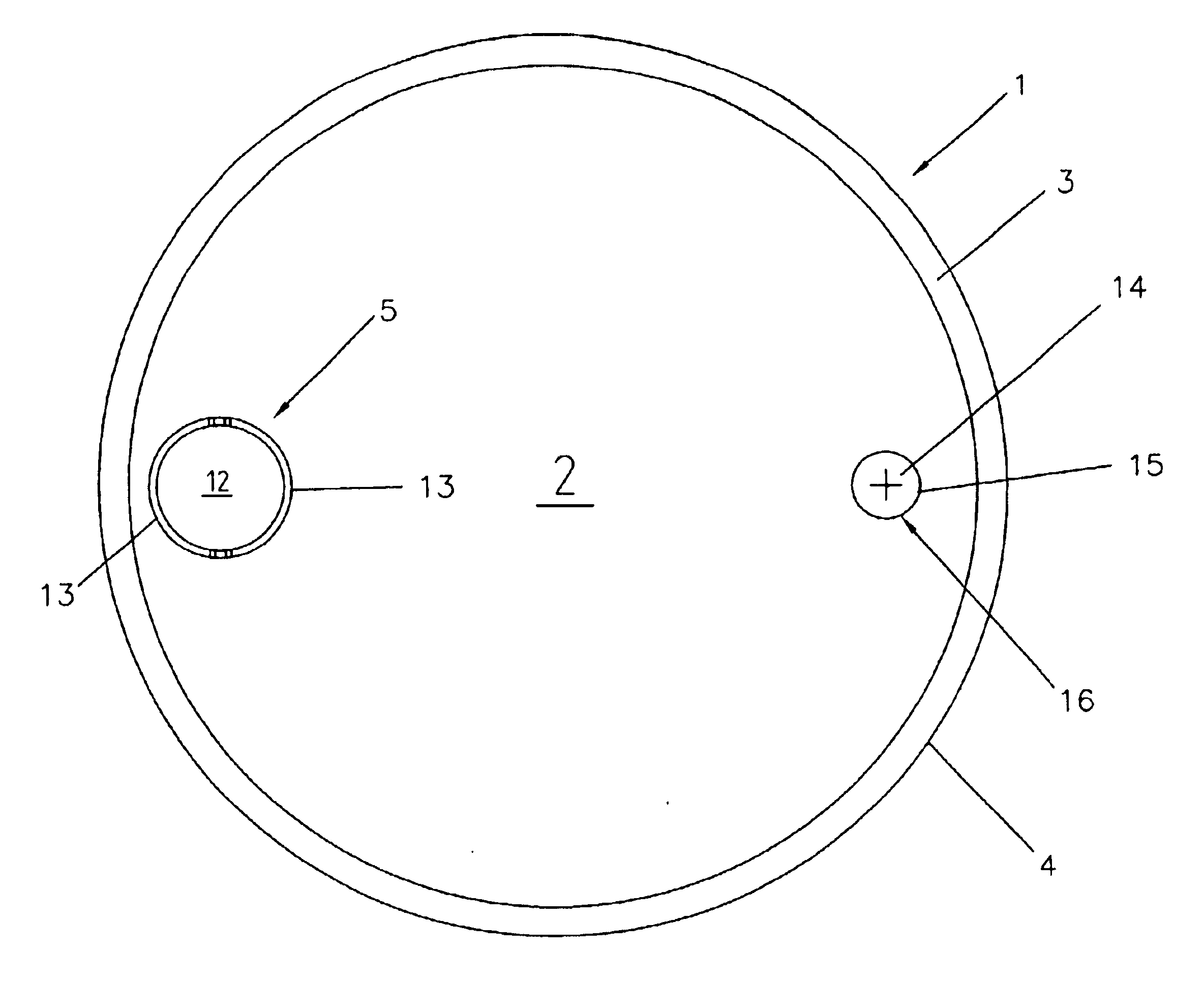
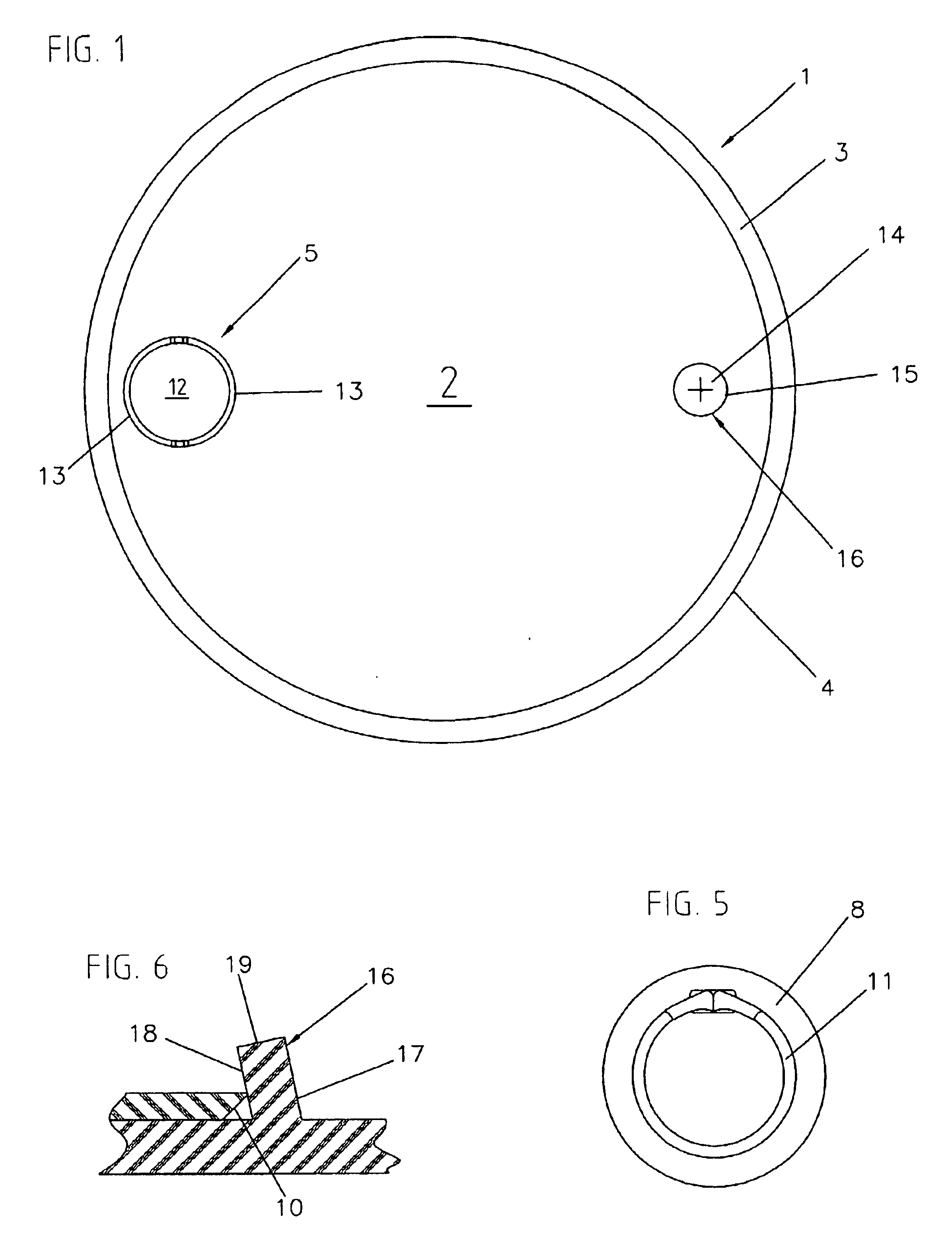
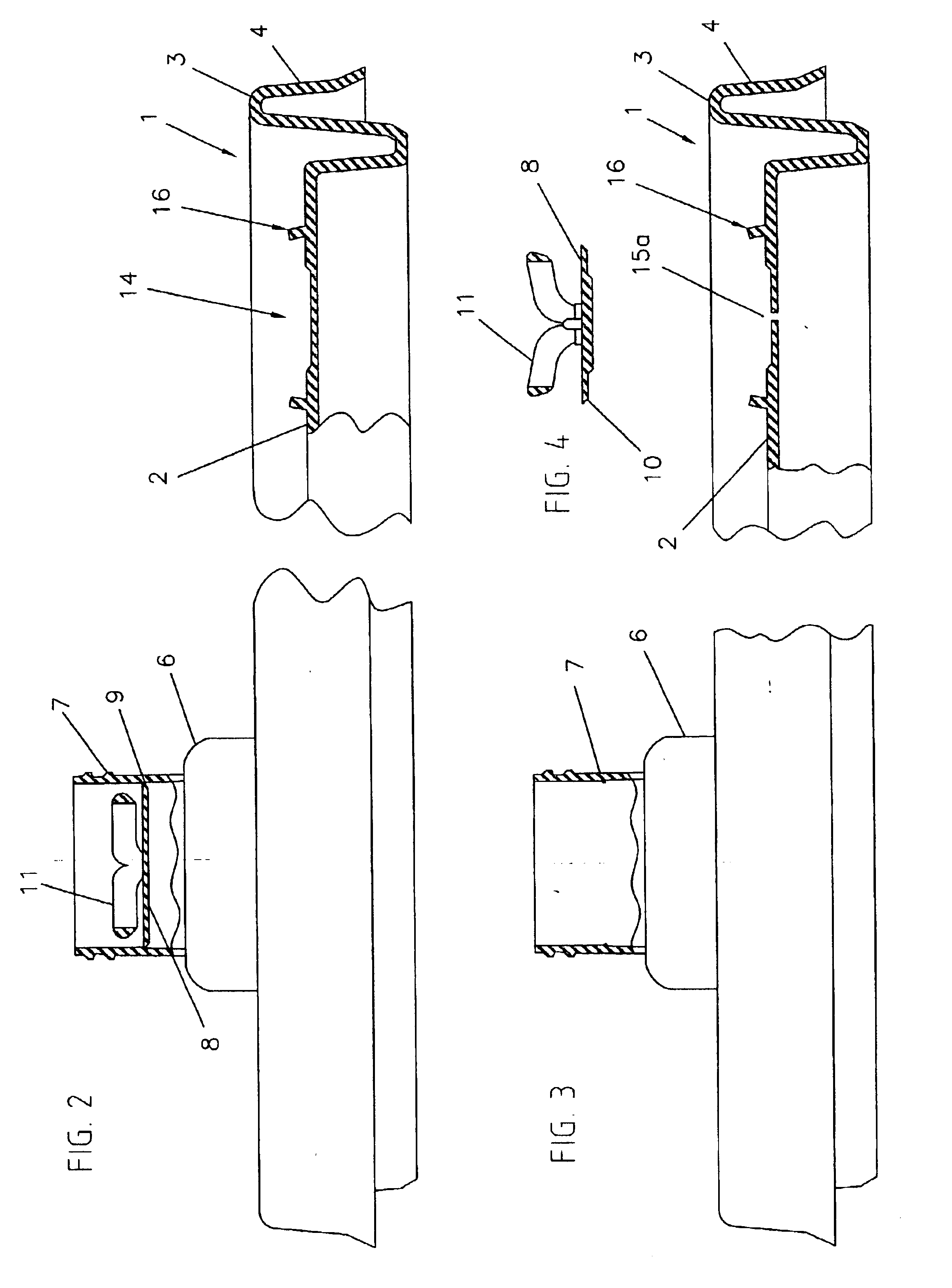
The pail lid of the invention generally indicated by numeral 1 has a disc like center panel 2 surrounded by a raised chime 3 which extends into an outer peripheral sidewall 4. A known flexible spout closure 5 such as the type disclosed in U.S. Pat. No. 6,386,405 is affixed to the pail lid center panel 2 at a position adjacent the chime 3 for convenient fluid dispensing. The closure 5 has a lower flexible wall 6 and an upper externally threaded neck 7. A disc like sealing diaphragm 8 is integrally molded within the neck 7 so as to close off the interior passage therethrough. The sealing diaphragm is integrally connected to the cylindrical interior surface of the neck 7 by an annular score line 9 to facilitate tearing. Immediately below the score line the sealing diaphragm is formed at its periphery with an inwardly and downwardly extending conical edge surface 10. A ring pull 11 suitable for reception of a persons finger is also integrally molded as part of the sealing diaphragm. A c...


PUM


Abstract

A plastic pail having a dispensing closure and a diametrically opposed puncture zone to enable surge free pouring. The dispensing closure has a flexible pouring spout and threaded overcap. The spout dispensing passage is closed off by a tear out sealing diaphragm in initial shipping condition The puncture zone is surrounded by an upstanding retaining collar dimensioned to receive the separated tear out diaphragm which acts as a protective cover for the punctured anti-glug vent during storage and handling.

Description

BACKGROUND OF THE INVENTIONIn the dispensing of fluid from relatively large volume containers such as closed pails or buckets, smooth rapid flow is best achieved by providing an air entry aperture in the pail lid diametrically opposite the dispensing opening. This is, of course, most easily achieved by simply punching a hole in the pail lid with an available implement such as a screwdriver with excellent pouring results. However, an open aperture in the pail top invites the entry of surface contaminants and is generally unacceptable. This can be overcome with the provision of a special opening formed in the pail lid into which a recloseable venting closure is inserted during the pail manufacture. This works very nicely but entails an objectionable added cost factor. Numerous more expensive self venting pouring spouts have entered the market which to a certain degree lessen the additional manufacturing cost by eliminating the added labor component but fall far short in pouring perfor...

Claims


Application Information

Patent Timeline
Patent Type & Authority Patents(United States)
IPC IPC(8): B65D47/06B65D47/10B65D51/16
CPCB65D47/063B65D51/1677B65D47/103
Inventor DWINELL, DAVIS B.
Owner AMERICAN FLANGE & MFG CO INC
Why Eureka
Try Eureka