Microwave applicator, plasma processing apparatus having same, and plasma processing method
a plasma processing apparatus and microwave technology, applied in the direction of arc welding apparatus, diaphragms, chemical vapor deposition coatings, etc., can solve the problem of not being able to detect microwave current at a location apart, and not being able to achieve uniform plasma and processing uniformity, etc. problem, to achieve the effect of accurate control of microwave radiation characteristics
- Summary
- Abstract
- Description
- Claims
- Application Information
AI Technical Summary
Benefits of technology
Problems solved by technology
Method used
Image
Examples
embodiment 1
(Embodiment 1)
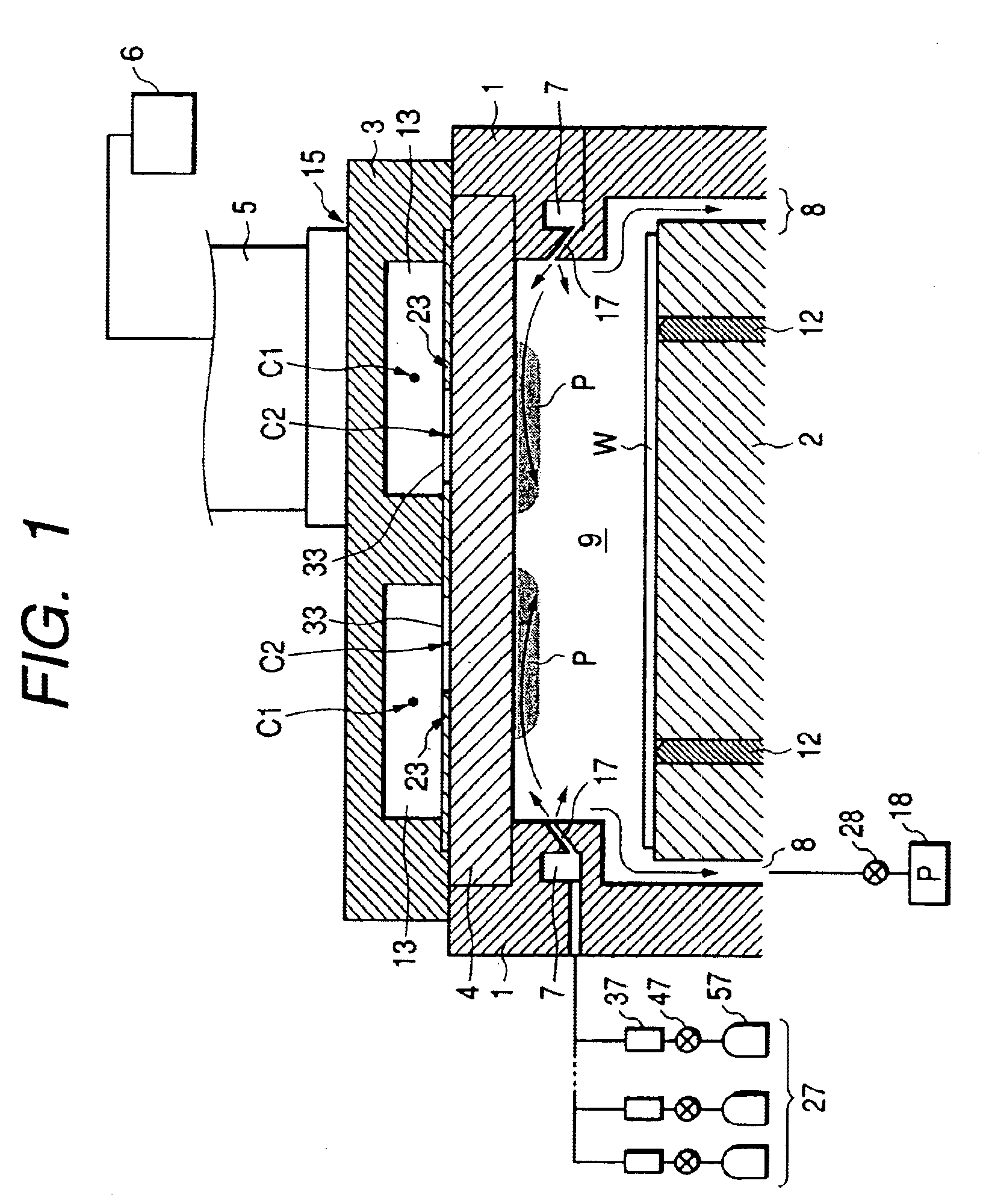
FIG. 1 is a schematic sectional view showing a plasma processing apparatus according to a preferred embodiment of the present invention.
The microwave applicator 3 comprising a circular waveguide 13 having a surface provided with a plurality of slots 33 for radiating microwaves is characterized in that the centers C2 of the plurality of slots 33 are offset in a direction parallel to the surface with respect to the center C1 of the circular waveguide 13.
Specifically, reference numeral 1 designates a vacuum container which can house the article to be processed W therein and generate a plasma in the plasma generation chamber 9 and is, for example, a container of an atmosphere-open-type or a container isolated from the atmosphere by a load lock chamber provided adjacent thereto (not shown).
Reference numeral 2 denotes an article holding means called “susceptor” or “holder” for housing the article W in the vacuum container 1 and holding the article, which has lift pins 12 tha...
embodiment 2
(Embodiment 2)
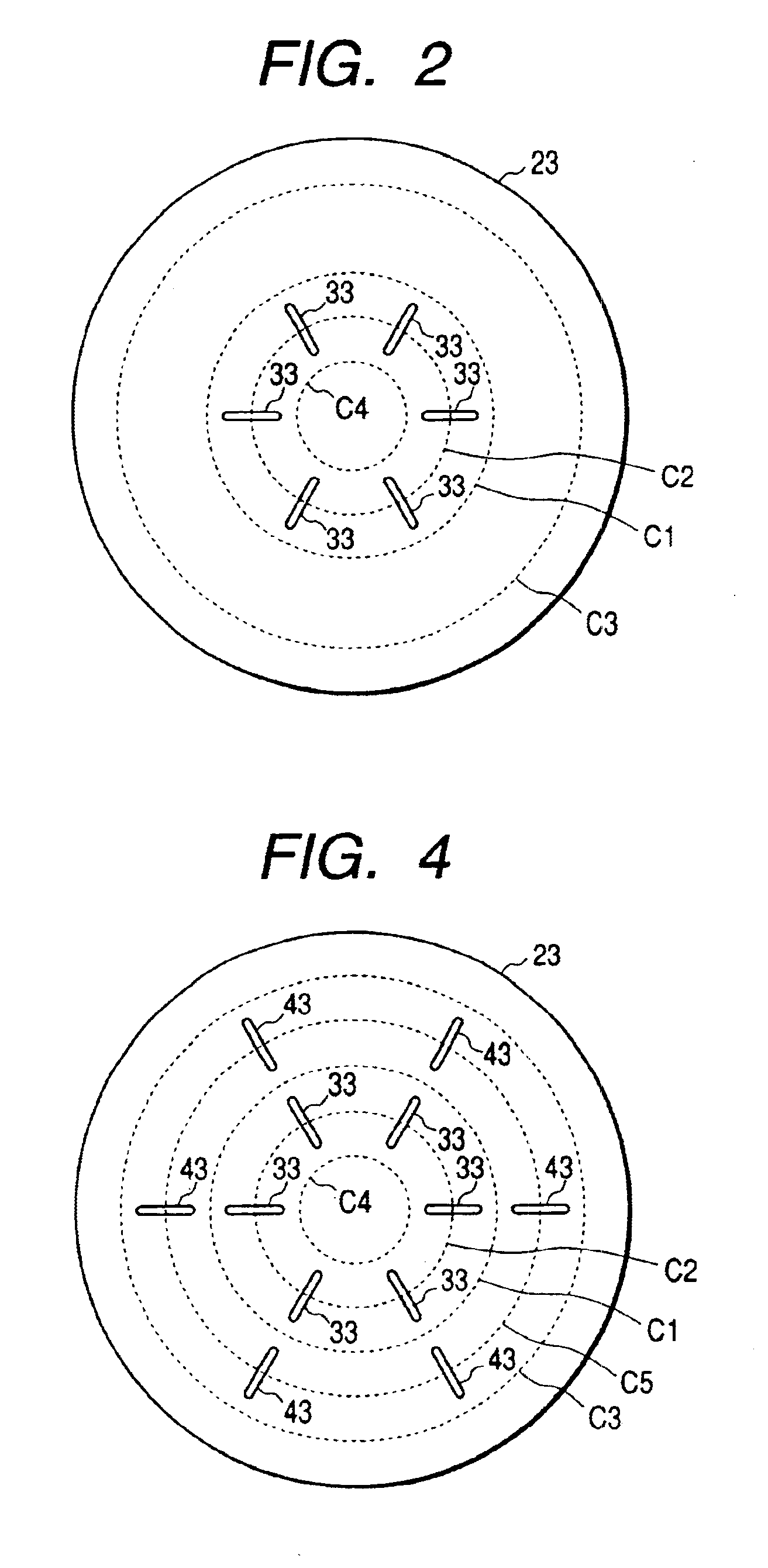
According to another preferred embodiment of the present invention, there is provided a microwave applicator comprising a circular waveguide having a flat surface provided with a plurality of slots for radiating microwaves, characterized in that the plurality of slots are discontinuous linear slots 33, 34 provided in a direction intersecting the microwave travelling direction.
FIG. 3 is a schematic sectional view showing such a plasma processing apparatus.
The apparatus has a slotted flat plate 23 as shown in FIG. 4. The apparatus is different from the apparatus of FIG. 1 in provision of the slotted flat plate 23 as shown in FIG. 4 and an article biassing power source 22.
The apparatus is configured such that the pressure inside of the space 9 can be reduced to control the plasma to broaden, and that plasma processing can be carried out while applying a bias voltage to the article from the bias power source 22. This configuration is suitable for etching processing.
Further...
embodiment 3
(Embodiment 3)
With reference to FIGS. 5 and 6, an endless circular waveguide according to another preferred embodiment of the present invention and a microwave plasma processing apparatus using the same are described.
FIG. 5 is a schematic longitudinal sectional view of a microwave plasma processing apparatus using a circular waveguide having a flat plate with discontinuous linear slots as a example of the present invention, and FIG. 6 is a plan view of the slotted plate of the circular waveguide of FIG. 5.
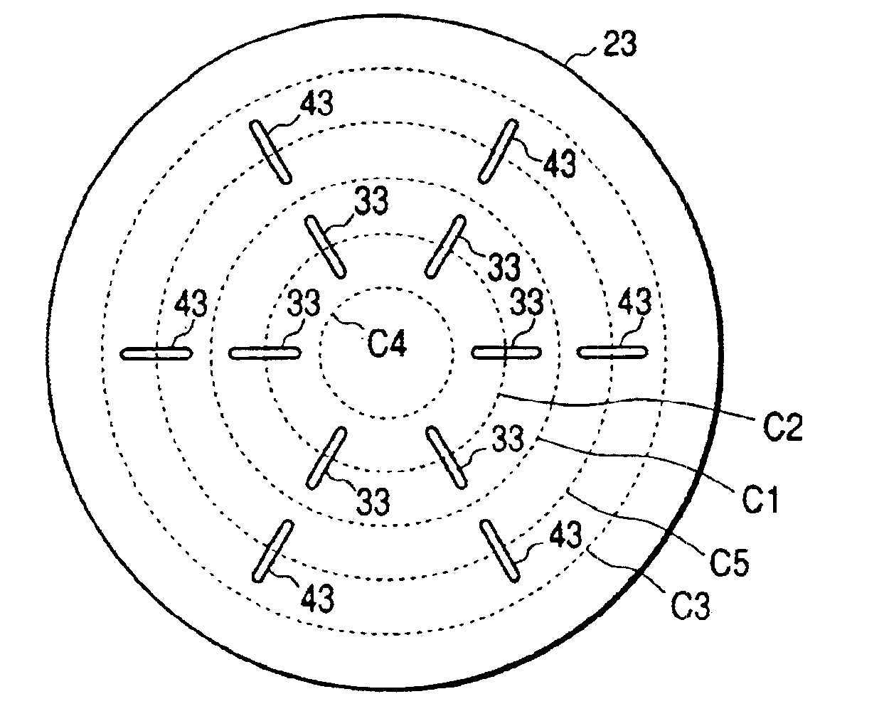
The apparatus is different from the apparatus shown in FIGS. 3 and 4 in that the size of the circular waveguide (microwave applicator) 3 is larger than that of the article W, that the gas supply port 17 is provided downward, and that there are eight pairs of discontinuous linear slots 33, 43 as offset inside and outside, respectively. Further, the holding means 2 is provided with a heater 114 for temperature control of the article W.
The exhaust system and gas supply system may be t...
PUM
| Property | Measurement | Unit |
|---|---|---|
| Length | aaaaa | aaaaa |
| Pressure | aaaaa | aaaaa |
| Dielectric polarization enthalpy | aaaaa | aaaaa |
Abstract
Description
Claims
Application Information
 - R&D
- Intellectual Property
- Life Sciences
- Materials
- Tech Scout
- Unparalleled Data Quality
- Higher Quality Content
- 60% Fewer Hallucinations
Browse by: Latest US Patents, China's latest patents, Technical Efficacy Thesaurus, Application Domain, Technology Topic, Popular Technical Reports.
© 2025 PatSnap. All rights reserved.Legal|Privacy policy|Modern Slavery Act Transparency Statement|Sitemap|About US| Contact US: help@patsnap.com


