Modified vortex for an ion mobility spectrometer

a technology of ion mobility and vortex, which is applied in the direction of mass spectrometers, instruments, separation processes, etc., can solve the problems of deficient method of concentrating using an absorbent substance, the operator's skill is not high enough, and the evaporation rate of low volatility particles is increased. , the effect of enhancing the

Inactive Publication Date: 2005-03-22
LEIDOS SECURITY DETECTION & AUTOMATION INC
View PDF6 Cites 31 Cited by
  • Summary
  • Abstract
  • Description
  • Claims
  • Application Information

AI Technical Summary

Benefits of technology

The spinning motion of the said emitted gas may be referred to as a vortex, cyclone, or a tornado. The spinning motion results in a radially-outward directed centrifugal force that restrains the emitted gas flow from immediately being drawn radially inward into the partial vacuum of the external sampling orifice. Eventually, friction with the surrounding ambient air will slow the emitted gas sufficiently that it will be drawn into the partial vacuum at some distance from the external sampling orifice. Depending on the flow of the emitted gas, this distance can be varied from near the external sampling orifice (low flow) to far from the external sampling orifice (high flow). The vortex motion in effect creates a virtual tube consisting of a surrounding wall of moving gas that behaves like an extension of the tube that formed the external sampling orifice.
The said heating of the said emitted gas may be employed in cooperation with the motion of the vortex flow to enhance the evaporation rate of low volatility particles on a target surface. While hot air will obviously warm the low volatility particles, the effect is significantly enhanced by the vortex flow, which is substantially tangential to the target surface for efficient transfer of heat. This tangential or parallel flow is in contrast to simply blowing hot air straight at the target surface, which would impinge normal to the surface with a much lower transfer of heat to that portion of the target surface where vapors can be drawn into the gas sampling orifice.

Problems solved by technology

However, this method of concentrating using an absorbent substance is deficient in that it tends to be relatively slow to implement and is subject to variations in the skill of the operator.
Additionally, while the absorber is relatively low in cost, the process of taking a great many samples becomes expensive in that the absorber generally should only be used once to ensure consistent results.
Therefore, it is sometimes useful to minimize unnecessary surfaces between the sampling orifice and the ion source.

Method used


Image

  • Modified vortex for an ion mobility spectrometer
  • Modified vortex for an ion mobility spectrometer
  • Modified vortex for an ion mobility spectrometer

Examples


Embodiment Construction

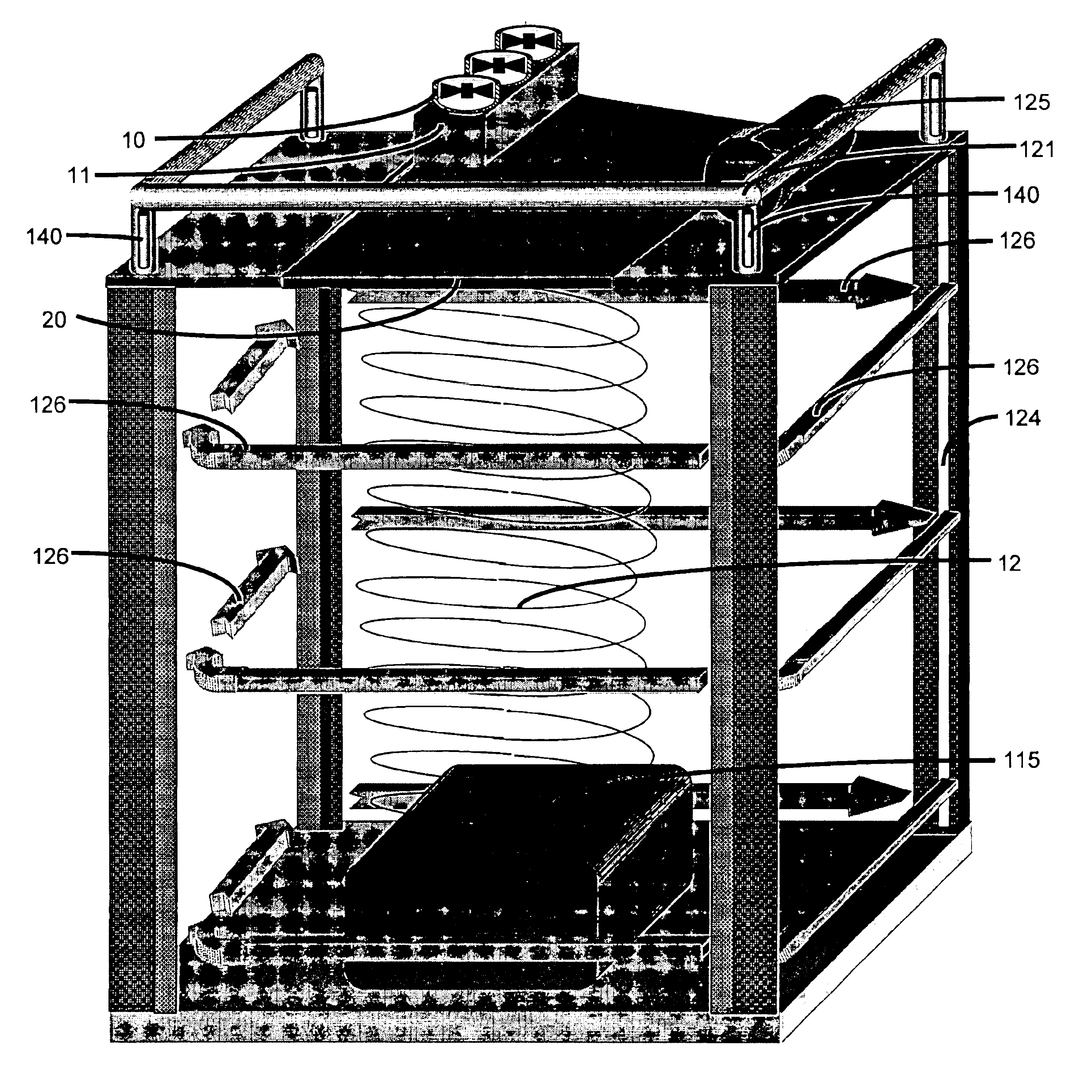
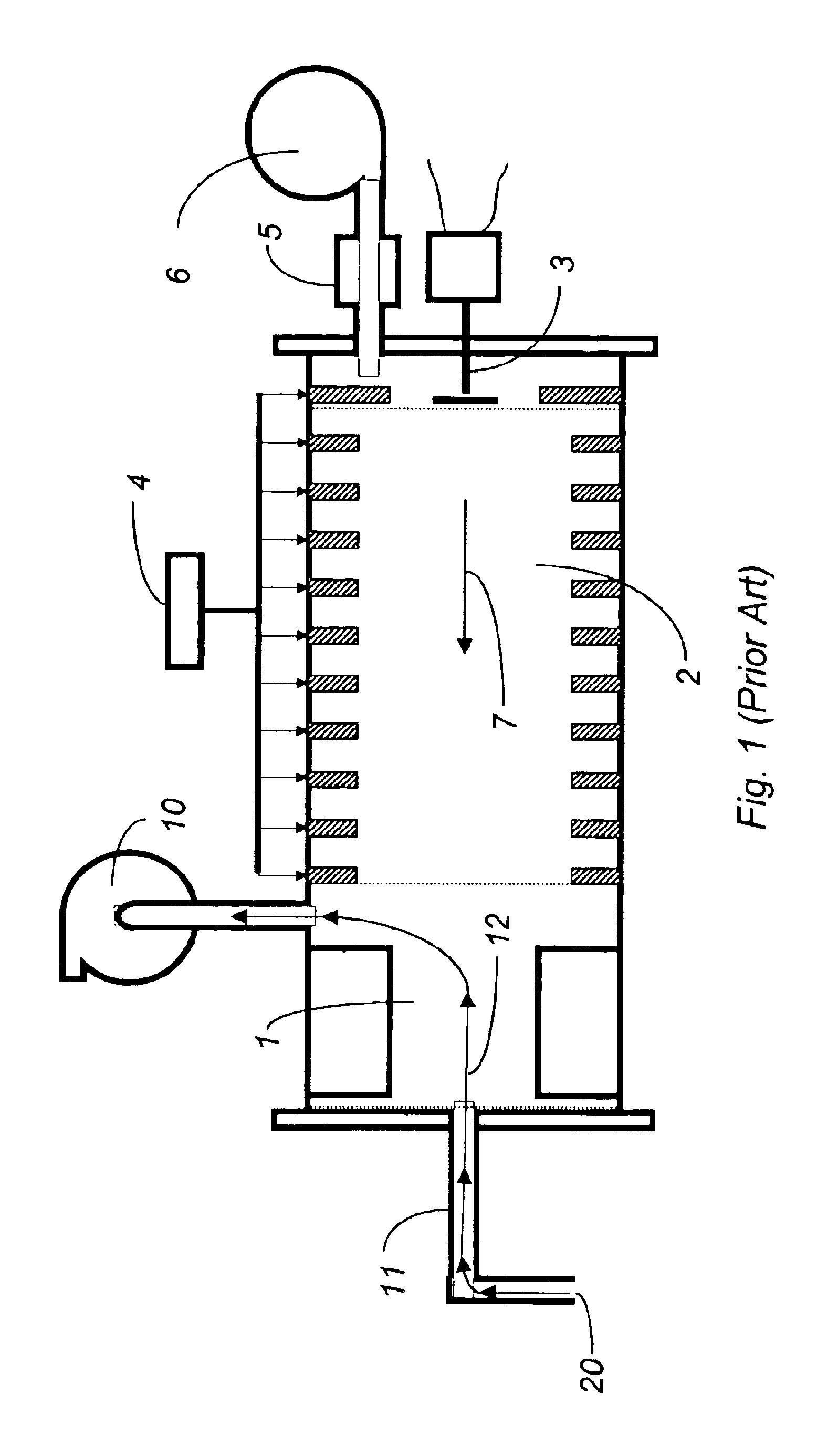
An IMS is illustrated in FIG. 1. While various embodiments may differ in details, FIG. 1 shows basic features of an IMS that may be used in connection with the system described herein. The IMS includes an ion source 1, a drift tube 2, a current collector 3, a source of operating voltage 4 and a source of purified drift gas 5, possibly with it own gas pump 6. An IMS may already include a gas pump for gas sampling 10 and a tubular connection 11 between the ion source 1 and an external gas sampling inlet 20 that includes an orifice. Gas flow for the drift gas 7 moves through the drift tube 2. Sampling gas flow 12 moves from the external gas sampling inlet 20 through the tubular connection 11 and ion source 1 to the gas sampling pump 10.

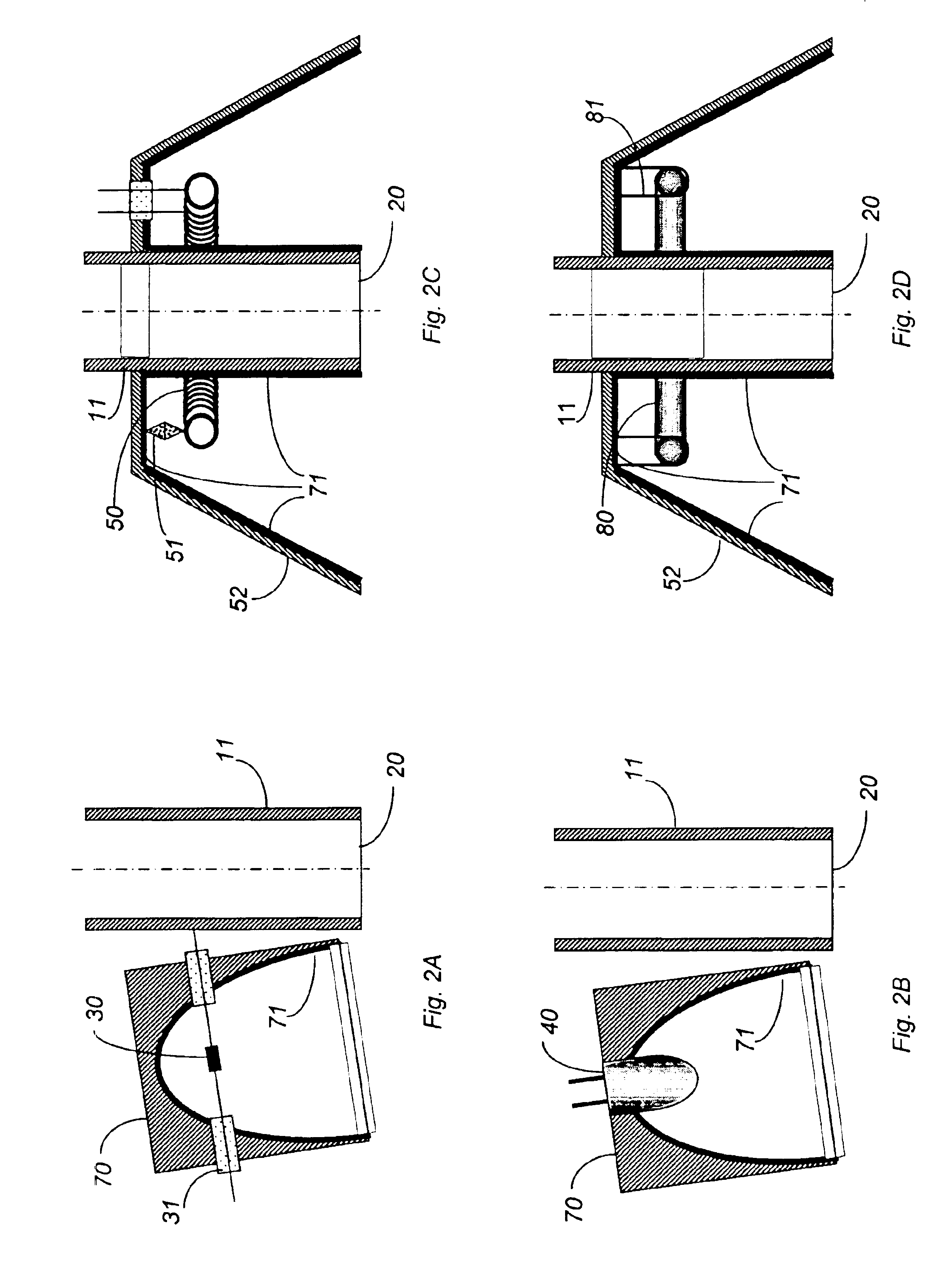
FIGS. 2A-2D show a selection of possible embodiments for a radiative heating element, provided proximal to the gas sampling inlet 20, that heats the target surface in conjunction with the gas sampling system of the IMS. In FIG. 2A, the technique for heat...


PUM


Abstract

The presence of trace molecules in air is often determined using a well-known device called an ion mobility spectrometer. Such devices are commonly utilized in the fields of explosives detection, identification of narcotics, and in applications characterized by the presence of very low airborne concentrations of organic molecules of special interest. The sensitivity of such instruments is dependent on the method of gas sampling utilized. The vortex sampling nozzle consists of an intake gas flow and a separate coaxial heated, emitted gas flow that is deflected to move with a circular motion. A heated vortex sampling nozzle can greatly improve the sampling efficiency for low volatility target molecules, particularly when the sampling needs to be performed at a distance from the air intake and the vapor pressure of the target molecules is very low. Additionally, the vortex air may contain one or more additional substances that promote vaporization, combine with the target molecule, or provide a known marker in the ion mobility time-of-flight spectrum.

Description

BACKGROUND OF THE INVENTION1. Field of the InventionThis invention relates to an ion mobility spectrometry instrument that detects chemicals present as vapors in air or other gases, or liberated as vapors from condensed phases, such as particles or solutions, and more particularly relates to the sampling of such vapors for injection into the ion source of the ion mobility spectrometer (IMS) when the source of vapors exhibits a relatively low vapor pressure.2. Description of Related ArtIMS instruments operate on the basis of the time taken by ionized molecules to move through a gas-filled drift region to a current collector while under the influence of an electric field. The ions are created in a gas-filled region called the ion source, which is connected to the drift region through an orifice or a barrier grid. The ion source may use any of a variety of techniques to ionize atoms and molecules. One or more flowing streams of gas enter the ion source through one or more orifices, and...

Claims


Application Information

Patent Timeline
Patent Type & Authority Patents(United States)
IPC IPC(8): B01D59/44B01D59/00H01J49/34H01J49/00H01J49/40
CPCG01N27/622G01N1/2211
Inventor KRASNOBAEV, LEONID YA.BUNKER, STEPHEN N.
Owner LEIDOS SECURITY DETECTION & AUTOMATION INC
Why Eureka
Try Eureka