Diversity receiver with joint baud clock recovery

a receiver and baud clock technology, applied in the field of diversity receivers, can solve the problems of bit errors, digital broadcast systems that can fail completely, and analog television signals degrade gracefully, so as to improve the overall bit error rate and increase the noise problem

Inactive Publication Date: 2005-03-22
AVAGO TECH INT SALES PTE LTD
View PDF8 Cites 13 Cited by
  • Summary
  • Abstract
  • Description
  • Claims
  • Application Information

AI Technical Summary

Benefits of technology

[0019]For example, suppose that the first RF signal in the first channel is a much stronger signal as compared to the second RF signal in the second channel. The first AGC loop amplifies the first RF signal very little, if at all, because it is already a strong signal. The second RF signal in the second channel is likely to be noisy because it is a relatively weak signal. In the prior art, the weaker noisy signal in the second channel would be greatly amplified by the AGC control loop of the second channel. Noise amplified in the AGC control loop second channel increases the noise problems and worsens the overall bit error rate when the first and second channels of the diversity receiver are combined equally.
[0020]In accordance with the present invention, the AGC control loop with the stronger first RF signal limits the maximum amount that the weaker signal is amplified in the AGC control loop with the weaker second RF signal. By limiting the AGC feedback signal in the control loop of the second channel to a maximum differential with respect to the AGC feedback signal in the control loop of the first channel, the weaker signal is not overly amplified. In such manner, the noise in the weaker noisy signal in the second channel would not be as greatly amplified by the joint AGC control loop of the second channel, as it would be in the case of an independent AGC loop.
[0027]In accordance with the present invention, a whole baud skew corrector is provided, which couples the first and second channels of the diversity receiver in a joint timing loop for baud clock recovery. In particular, after the joint loop filter of the joint timing loop settles down near steady state frequency and phase for each respective baud clock, the whole baud skew corrector is enabled.

Problems solved by technology

While analog television signals degrade gracefully in the presence of interference, digital broadcast systems can fail completely when the bit error rate overcomes the error tolerance of the system.
Bit errors result from weak signals, noisy signals or signals subject to fading and distortion.
Furthermore, these obstructions reflect the transmitted signal such that multiple versions with varying amplitudes, phases and time delays are simultaneously received.
The indoor environment is even more complicated since there is rarely an unobstructed path between the transmitter and receiver antennas.
Furthermore, objects causing signal reflection and absorbtion are numerous and are often in motion.
Reception of the transmitted signal along multiple paths from the transmitter to the receiver causes signal distortion which manifests itself in a variety of ways.
The different paths have different delays that cause replicas of the same signal to arrive at different times (like an echo) and sum at the receiver antenna, causing inter-symbol interference.
The phases of these multipath signals may combine constructively or destructively resulting in large range of possible signal strengths.
Indoor signals typically have severe multi-path distortions and are changing rapidly in time, ranging from flat fades to deep in-band nulls to relatively unimpaired signals.
Conventional indoor TV antennas and outdoor antennas used with existing 8VSB receivers often do not produce reliable and uninterrupted reception of digital broadcast HDTV signals.

Method used


Image

  • Diversity receiver with joint baud clock recovery
  • Diversity receiver with joint baud clock recovery
  • Diversity receiver with joint baud clock recovery

Examples


Embodiment Construction

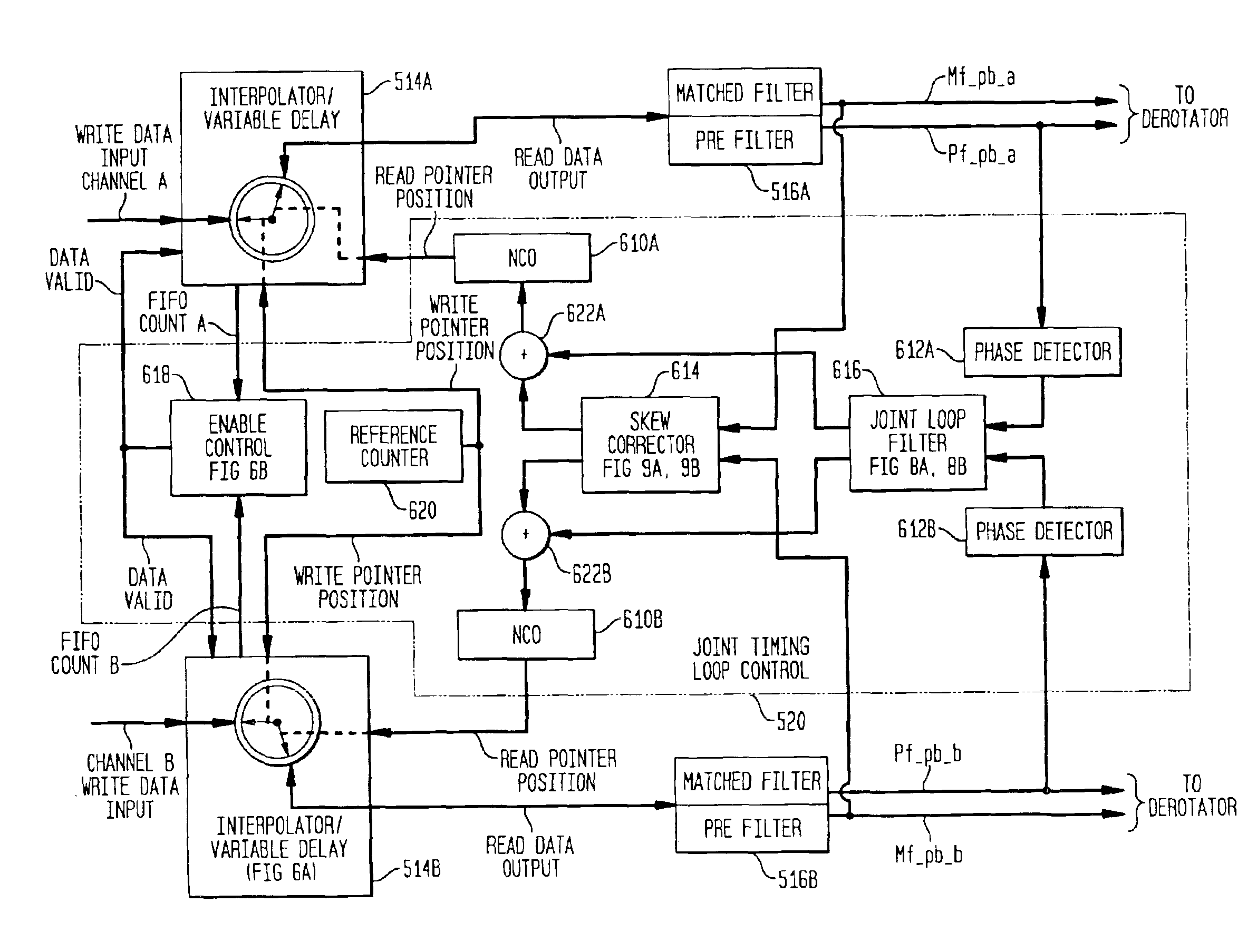
[0047]FIG. 6B is a block diagram of the enable control logic 618 in the joint timing loop for baud clock recovery of FIG. 6 for use in conjunction with the present invention.

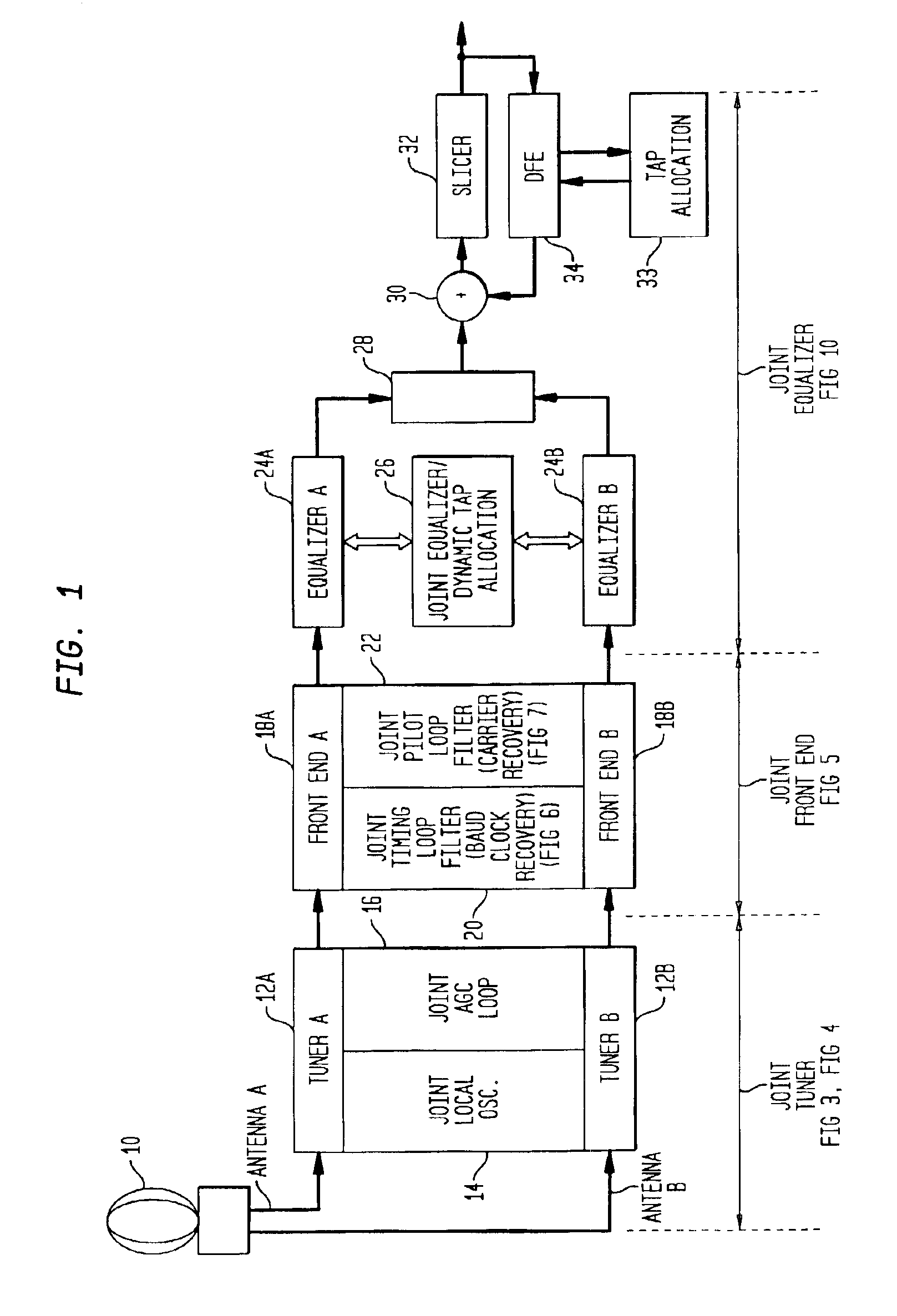
[0048]FIG. 7 is a block diagram of a joint pilot loop for RF carrier recovery for use in a multiple channel diversity receiver in accordance with the present invention.

[0049]FIG. 8A is a block diagram of a generalized joint loop filter in accordance with the present invention for use in the joint timing loop of FIG. 6 and joint pilot loop of FIG. 7.

[0050]FIG. 8B is a block diagram of a specific joint loop filter in accordance with the present invention for use in the joint timing loop of FIG. 6 and joint pilot loop of FIG. 7.

[0051]FIG. 9A is a block diagram partially in flow chart form of the skew corrector logic 614 in FIG. 6 in accordance with the present invention.

[0052]FIG. 9B is a flow chart diagram of the control logic 926 in FIG. 9A embodying the present invention.

[0053]FIG. 9C is an illustration of time ...


PUM


Abstract

First and second RF signals in the respective first and second channels of a multiple channel diversity receiver are processed jointly in a joint timing loop filter for baud clock recovery. The channel with the stronger signal determines the frequency of the baud clock for the channel with the weaker signal, leaving the respective PLL's to make individual phase adjustments for each channel. The first and second channels also share a skew corrector for baud clock recovery when the multipath delay between the first and second RF signals is greater than one whole baud clock period. The whole baud skew corrector computes the correlation between the first and second received signals, and if the correlation is low, shifts the first and second signals by one whole baud and recomputes the correlation. The process of shifting the first and second received signals and computing the correlation function is repeated for various whole baud shifts in accordance with a search strategy to find the best (highest) correlation.

Description

[0002]This is a divisional of co-pending application Ser. No. 09 / 363,813, filed on Jul. 30, 1999 U.S. Pat. No. 6,560,299.FIELD OF THE INVENTION[0003]The present invention relates to diversity receivers.BACKGROUND OF THE INVENTION[0004]Conventional television signals transmit video information in analog form by modulating the amplitude and frequency of a carrier signal. Digital television systems convert an analog video signal into digital information, which is transmitted by pulse modulating the amplitude and phase of a carrier signal. For example, in broadcasting high definition television (HDTV), digital information is transmitted by an 8 level amplitude modulation technique, known as 8VSB (vestigial sideband). In 8 VSB, modulation of a carrier to one of 8 levels (i.e., one of 8 symbols) defines 3 bits of digital information for each symbol clock interval. While analog television signals degrade gracefully in the presence of interference, digital broadcast systems can fail complet...

Claims


Application Information

Patent Timeline
Patent Type & Authority Patents(United States)
IPC IPC(8): H04B7/08H04L27/00H04L27/06
CPCH04B7/0848H04L7/005H04L27/066H04L7/0029H04L2027/003H04L2027/0057
Inventor STROLLE, CHRISTOPHER HSHAH, ANAND MENDRES, THOMAS JHULYALKAR, SAMIR NSCHAFFER, TROY A
Owner AVAGO TECH INT SALES PTE LTD
Why Eureka
Try Eureka