Plastic optical fiber, optical fiber cable, plugged optical fiber cable, and production methods thereof

a technology of plastic optical fiber and plugged fiber, which is applied in the direction of cladding optical fiber, instruments, other domestic articles, etc., can solve the problems of poor workability, inability to resist bending stress, and inorganic glass optical fiber is expensive, and achieves excellent heat resistance and small shrinkage ratio

Inactive Publication Date: 2005-03-22
MITSUBISHI CHEM CORP
View PDF18 Cites 18 Cited by
  • Summary
  • Abstract
  • Description
  • Claims
  • Application Information

AI Technical Summary

Benefits of technology

According to the present invention, a plastic optical fiber, an optical fiber cable and a plugged optical fiber cable which have a small shrinkage ratio and excellent heat resistance can be provided.

Problems solved by technology

However, the inorganic glass optical fiber is expensive, has poor workability, and is not so resistant to bending stress.
However, since the glass transition temperature (hereinafter referred to as “Tg”) of polymethyl methacrylate is as high as 100 to 115° C., its application is limited in view of heat resistance.
However, the method disclosed in Japanese Patent Application Laid-Open No. 16905-1992 cannot improve the heat resistance of a POF since the annealing temperature is lower than the Tg of the core by 50° C. or more and the annealing time is short.
Further, the invention disclosed in Japanese Patent Application Laid-Open No. 18608-1983 has the problem that even if the heat resistance of a material used in the protective layer is improved, a core itself is thermally shrunk when the temperature used gets close to the Tg of the core.
Further, Japanese Patent Application Laid-Open No. 11128-1993 is about the internal structure of a heating furnace used for the annealing, and since an appropriate annealing time and tension when a POF is heated at a predetermined annealing temperature are not set, the effect of reducing the thermal shrinkage of a POF is not satisfactory.
However, since this method cannot remove inner strain of a POF sufficiently, it cannot improve the heat resistance of the POF to a satisfactory level.
Further, when the temperature of a non-contact heating furnace is raised to remove the inner strain, the orientation of polymer chains cannot be maintained, thereby causing decrease in the mechanical strength of the POF and an increase in the non-uniformity of the diameter of the POF.
When these conventional POFs are used in optical communication or a sensor in a high temperature environment, e.g., in an engine room of an automobile or the like or in the interior of an automobile in mid summer, they are thermally shrunk, thereby causing decrease in optical transmission properties or trouble in wiring in a connector or the like.

Method used


Image

  • Plastic optical fiber, optical fiber cable, plugged optical fiber cable, and production methods thereof
  • Plastic optical fiber, optical fiber cable, plugged optical fiber cable, and production methods thereof
  • Plastic optical fiber, optical fiber cable, plugged optical fiber cable, and production methods thereof

Examples


examples 8 to 13

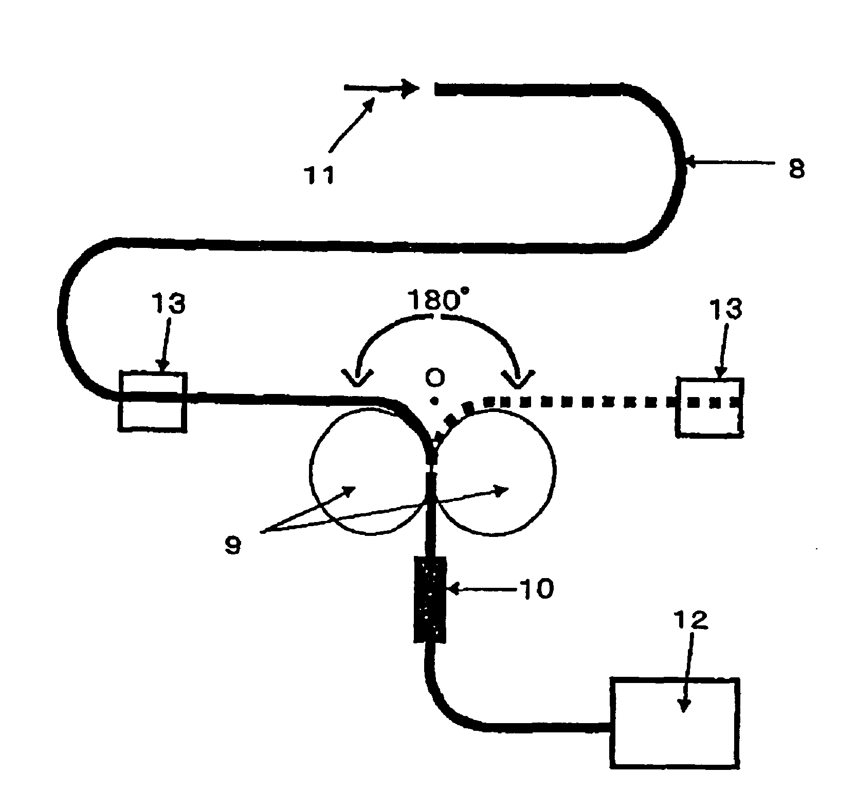
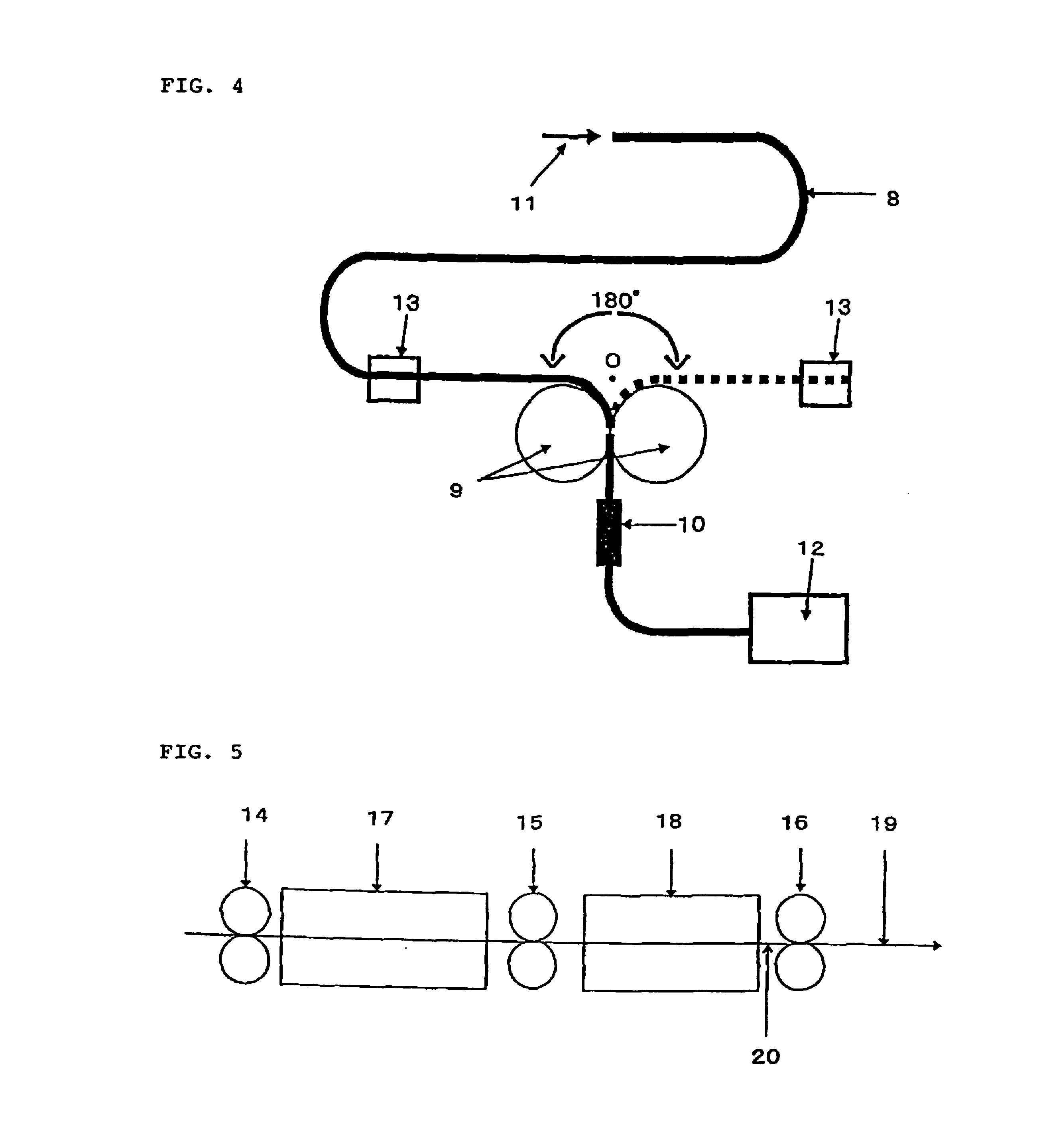
The POF obtained in Comparative Example 6 was heat treated at a temperature of the non-contact heating furnace 6 having a furnace length of 3 m of 165° C., a circumferential velocity ratio (circumferential velocity of the roller 4 / circumferential velocity of the roller 3) of 1.0, and roller circumferential velocities which were adjusted such that an annealing time would be 10 seconds, and the POF was then wound around a bobbin (Example 8). Then, the POF obtained in Example 8 was heat treated under the same conditions as used in Example B (using only the second device shown in FIG. 3), and the resulting POF was wound around a bobbin (Example 9). Thus, annealing of the POF was repeated under the same conditions as used in Example 8 for the numbers of times shown in Table 2 to obtain POFs which undergone the annealing for a different number of times (Examples 10 to 13).

The thermal shrinkage ratios of the obtained POFs are shown in Table 2. As is obvious from Table 2, POFs having smalle...

examples 14 , 15 and 16

Examples 14, 15 and 16

The POF obtained in Example 8 was subjected batch-type fixed-length annealing at 90° C. for 20 hours by using a commercially available hot air dryer in a similar manner (Example 14). Similarly, the POFs obtained in Examples 10 and 13 were subjected the batch-type fixed-length annealing (Examples 15 and 16). The results are shown in Table 3. POFs having further smaller thermal shrinkage ratios and excellent heat resistance could be obtained by the batch-type fixed-length annealing.

TABLE 3ThermalShrinkageRatio (%)RemarksExample 140.5POF of Example 8 was subjected to thefixed-length annealing at 90° C. for 20hours.Example 150.4POF of Example 10 was subjected tothe fixed-length annealing at 90° C. for20 hours.Example 160.3POF of Example 13 was subjected tothe fixed-length annealing at 90° C. for20 hours.

As described above, POFs obtained by the method (second invention) of the present invention, that is, POFs which satisfy the above annealing conditions, have a shri...

examples 17 and 18

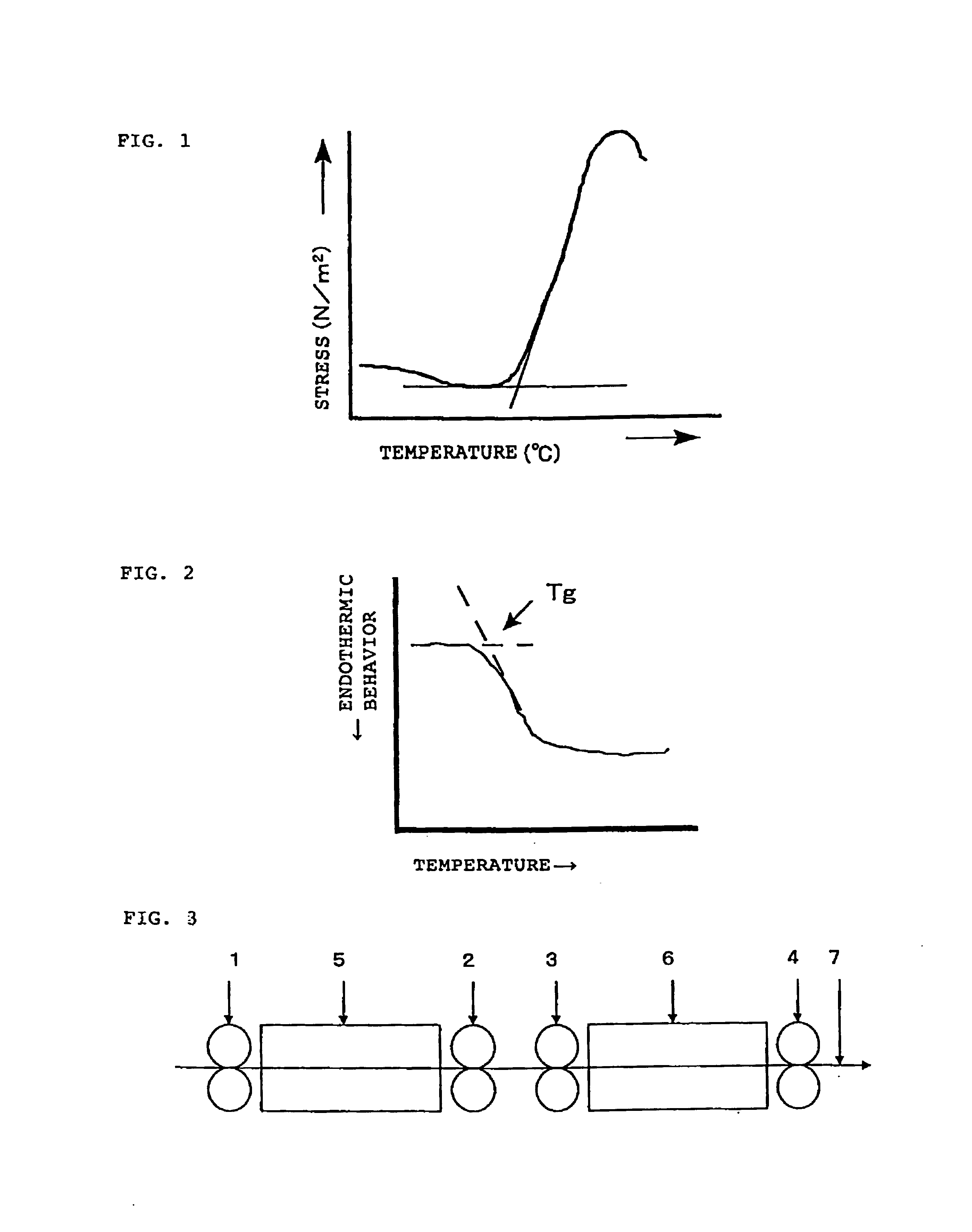
Polymethyl methacrylate obtained by continuous bulk polymerization was used as a core. The Tg of the core was 112° C. (DSC method, temperature rising rate: 10° C. / min). A copolymer of 51 parts by weight of 2,2,2-trifluoromethyl methacrylate, 30 parts by weight of 1,1,2,2-tetrahydroperfluorodecyl methacrylate, 18 parts by weight of methyl methacrylate and 1 part by weight of methacrylic acid was used as a sheath. A copolymer of vinylidene fluoride / tetrafluoroethylene=80 / 20 (mol %) was used as a material for a protective layer.

An undrawn POF comprising a core, a sheath and a protective layer was prepared from these polymers by means of a melt spinning method. The obtained undrawn POF was drawn at a roller circumferential velocity ratio (circumferential velocity of the roller 2 / circumferential velocity of the roller 1) of 2.7 by means of the drawing device (first device shown in FIG. 3) comprising the non-contact heating furnace 5 set at 160° C. and having a furnace length of 2.5 m and...


PUM

PropertyMeasurementUnit
shrinkage ratioaaaaaaaaaa
Tgaaaaaaaaaa

Abstract

The present invention relates to a production method of a plastic optical fiber which comprises the steps of heat drawing an undrawn plastic optical fiber obtained by melt spinning and annealing the drawn fiber at a circumferential velocity ratio between the front and rear rollers (circumferential velocity of a rear roller/circumferential velocity of a front roller) of 0.5 to 1.2 under heating conditions which satisfy 4≦y≦−1.5x+330 and (Tgc−5)° C.≦x≦(Tgc+110)° C. [Tgc: a glass transition temperature of a core, x: an annealing temperature (° C.), and y: an annealing time (seconds)]. According to the present invention, a plastic optical fiber having a small thermal shrinkage ratio and excellent heat resistance can be provided.

Description

TECHNICAL FIELDThe present invention relates to a plastic optical fiber, an optical fiber cable and a plugged optical fiber cable which are excellent in heat resistance, and production methods thereof.BACKGROUND ARTHeretofore, as an optical fiber, an inorganic glass optical fiber capable of excellent optical transmission over a wide wavelength range has been known and practically used mainly in a trunk line system. However, the inorganic glass optical fiber is expensive, has poor workability, and is not so resistant to bending stress. Therefore, a plastic optical fiber which is less expensive and in which making diameter large, the work of end faces and handling are easy has been developed and put to practical use in some fields of lighting, sensors, and wiring for communication between OA or FA equipment.Generally, a plastic optical fiber (hereinafter referred to as “POF”) is a fiber comprising a core-sheath structure in which as a core, a polymer having a large refractive index an...

Claims


Application Information

Patent Timeline
Patent Type & Authority Patents(United States)
IPC IPC(8): B29C55/04B29D11/00G02B6/10
CPCB29C55/045B29D11/00721G02B6/105G02B6/02033G02B6/02038G02B6/00
Inventor FUKUBA, YOSHINORIAKITA, TAKASHIIRIE, KIKUESUMI, TOSHINORIOKAMOTO, MASASHIOKUMURA, JUNSASAKI, SHIGEAKI
Owner MITSUBISHI CHEM CORP
Why Eureka
Try Eureka