

Automated header brazing machine
a header brazing machine and automatic technology, applied in the direction of soldering apparatus, manufacturing tools,auxillary welding devices, etc., can solve the problems of manual brazing process, high labor intensity, and slow process of tactile sensor use, and achieve high degree of repeatability
- Summary
- Abstract
- Description
- Claims
- Application Information
AI Technical Summary
Benefits of technology
Problems solved by technology
Method used
Image

Examples
Embodiment Construction
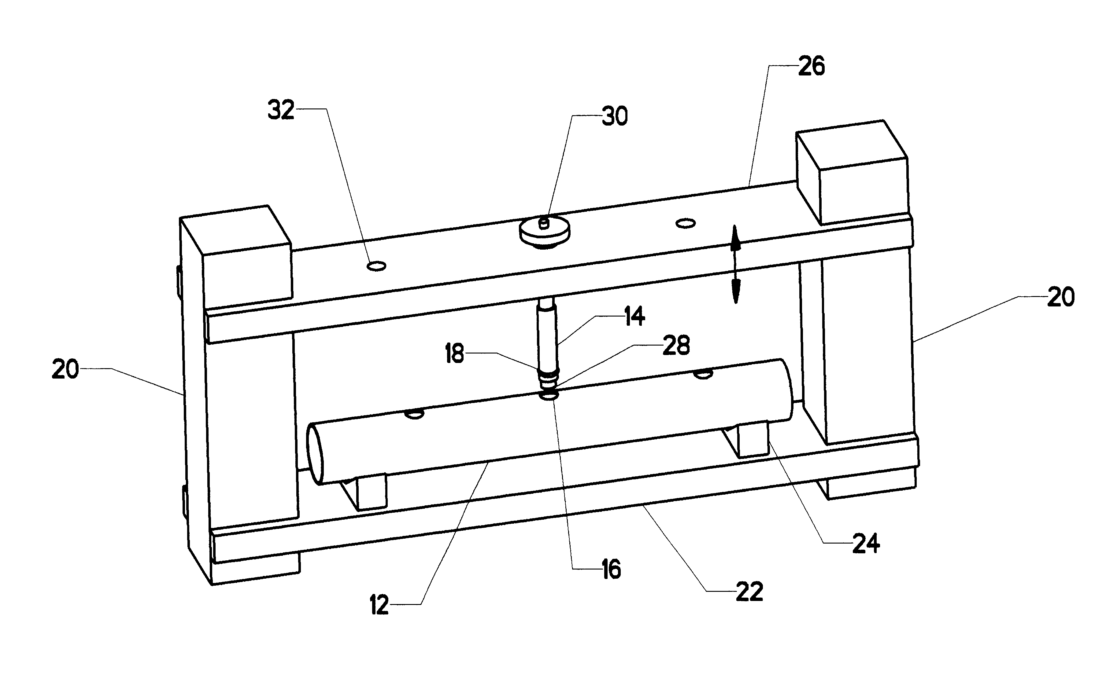
Prior to the commencement of the brazing process, it is important to hold the junction tubes in the correct position relative to the header. FIG. 5 shows a simple version of an appropriate fixture. A very simple header 12 is shown. Two main brackets 20 support the fixtures. A header bracket 22, with at lease two header supports 24, holds header 12 in place. Tube bracket 26 is vertically adjustable relative to the two main brackets 20. In the view as shown, a single tube holder 28 has been attached to tube bracket 26 by tube nut 30. Open positions 32 are available for the addition of more tube holders 28 but, in this simple version, only one is needed.
Those skilled in the art will know that header assemblies are manufactured with junction tubes in many different locations. Thus, a variety of different tube brackets 26 will often be used, with each one corresponding to a particular type of header (or possibly having adjustments to accommodate several different types).
In application, t...
PUM
| Property | Measurement | Unit |
|---|---|---|
| temperature | aaaaa | aaaaa |
| shape | aaaaa | aaaaa |
| heat | aaaaa | aaaaa |
Abstract
Description
Claims
Application Information