Apparatus and method for preparing and delivering fuel

a technology for preparing and delivering fuel, applied in lighting and heating apparatus, combustion types, instruments, etc., can solve the problems of high emissions, inability to apply many conventional fuel delivery methods (e.g. pressure atomization, twin-fluid or duplex atomization, ultrasonic atomization) to small-scale systems, and the effect of the preparation method is significan

Inactive Publication Date: 2005-03-29
PHILIP MORRIS USA INC
View PDF31 Cites 46 Cited by
  • Summary
  • Abstract
  • Description
  • Claims
  • Application Information

AI Technical Summary

Benefits of technology

One object is to provide a fuel preparation and delivery apparatus and method of delivering a vaporized stream of fuel to an application, without the need for operating fuel pressures above those found in typical automotive applications, a secondary atomizing fluid (e.g. air or steam), or high power consumption.
Another object is to provide a fuel preparation and delivery system and method that can produce vaporized streams of fuel to overcome the longstanding problems associated with the start-up of burners and engines.
It is a still further object to provide a fuel preparation and delivery system that can produce vaporized streams of fuel with a very short warm-up time.
One form of the means for cleaning can include an oxidizer control valve for placing the at least one capillary flow passage in fluid communication with an oxidizer, the heat source being operable to heat the oxidizer in the at least one capillary flow passage to a level sufficient to oxidize deposits formed during the heating of the liquid fuel. The oxidizer control valve serves to alternate between the introduction of liquid fuel and the introduction of oxidizer into the capillary flow passage and enable in-situ cleaning of the capillary flow passage when the oxidizer is introduced into the at least one capillary flow passage. The oxidizer is preferably selected from the group of air, exhaust gas, steam and mixtures thereof.
Yet another form of the means for cleaning deposits can include a solvent control valve for placing the at least one capillary flow passage in fluid communication with a solvent. The solvent control valve serves to alternate between the introduction of liquid fuel and the introduction of solvent into the capillary flow passage and enable in-situ cleaning of the capillary flow passage when the solvent is introduced into the at least one capillary flow passage.

Problems solved by technology

The liquid fuel preparation method has a very significant impact on the resultant emissions, particularly emissions of carbon monoxide (CO), unburned hydrocarbons (HC) and soot.
Large droplets evaporate slowly and may not have time to fully evaporate and react before exiting the combustion chamber, thereby resulting in higher emissions.
In addition, these small-scale systems require simple fuel delivery systems that do not use large amounts of power to prepare the fuel.
Thus many of the conventional fuel delivery approaches (e.g. pressure atomization, twin-fluid or duplex atomization, ultrasonic atomization) cannot be applied to small-scale systems: flow rates are too high; droplets are too large, required supply pressures are too high or an additional atomizing fluid is required.
Thus many small-scale combustion systems are limited to gaseous fuels.
While the use of supercritical pressures and temperatures might reduce clogging of the atomizer, it appears to require the use of a relatively more expensive fuel pump, as well as fuel lines, fittings and the like that are capable of operating at these elevated pressures.

Method used


Image

  • Apparatus and method for preparing and delivering fuel
  • Apparatus and method for preparing and delivering fuel
  • Apparatus and method for preparing and delivering fuel

Examples


example 1

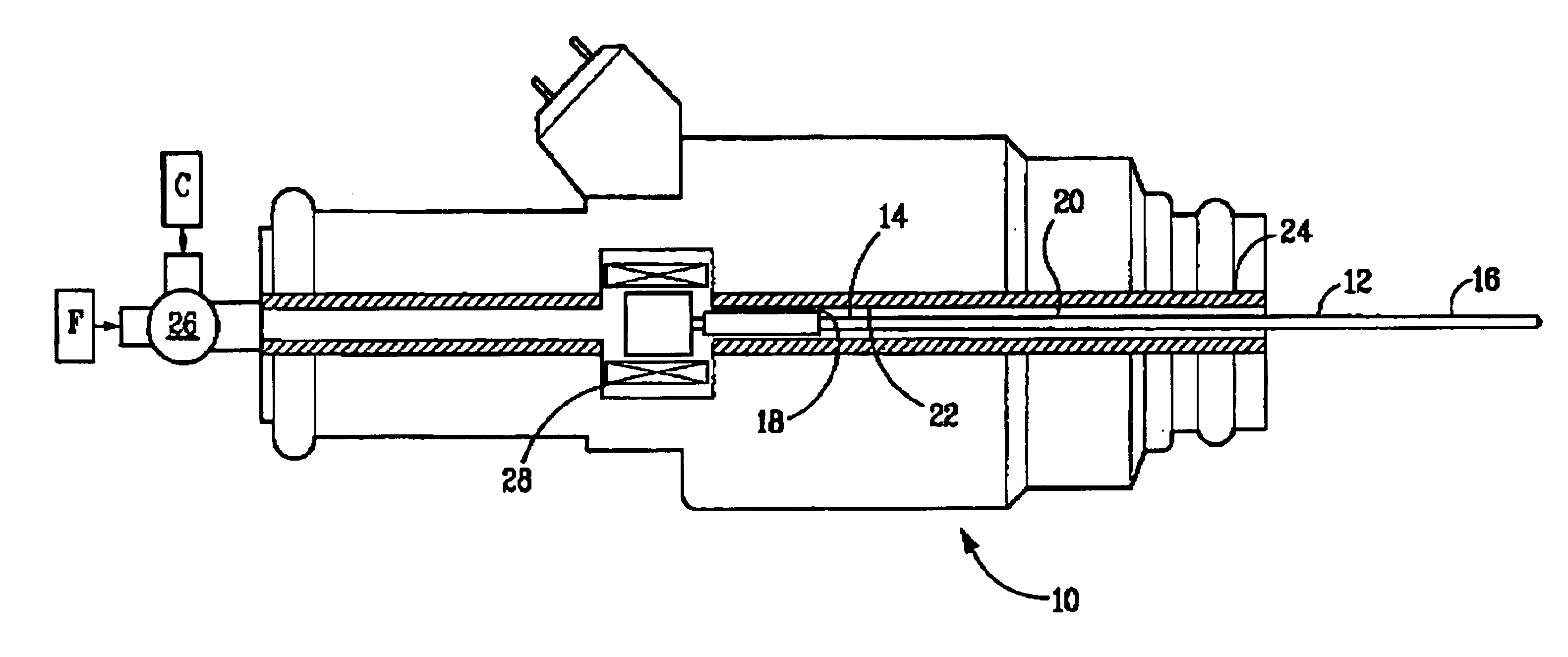
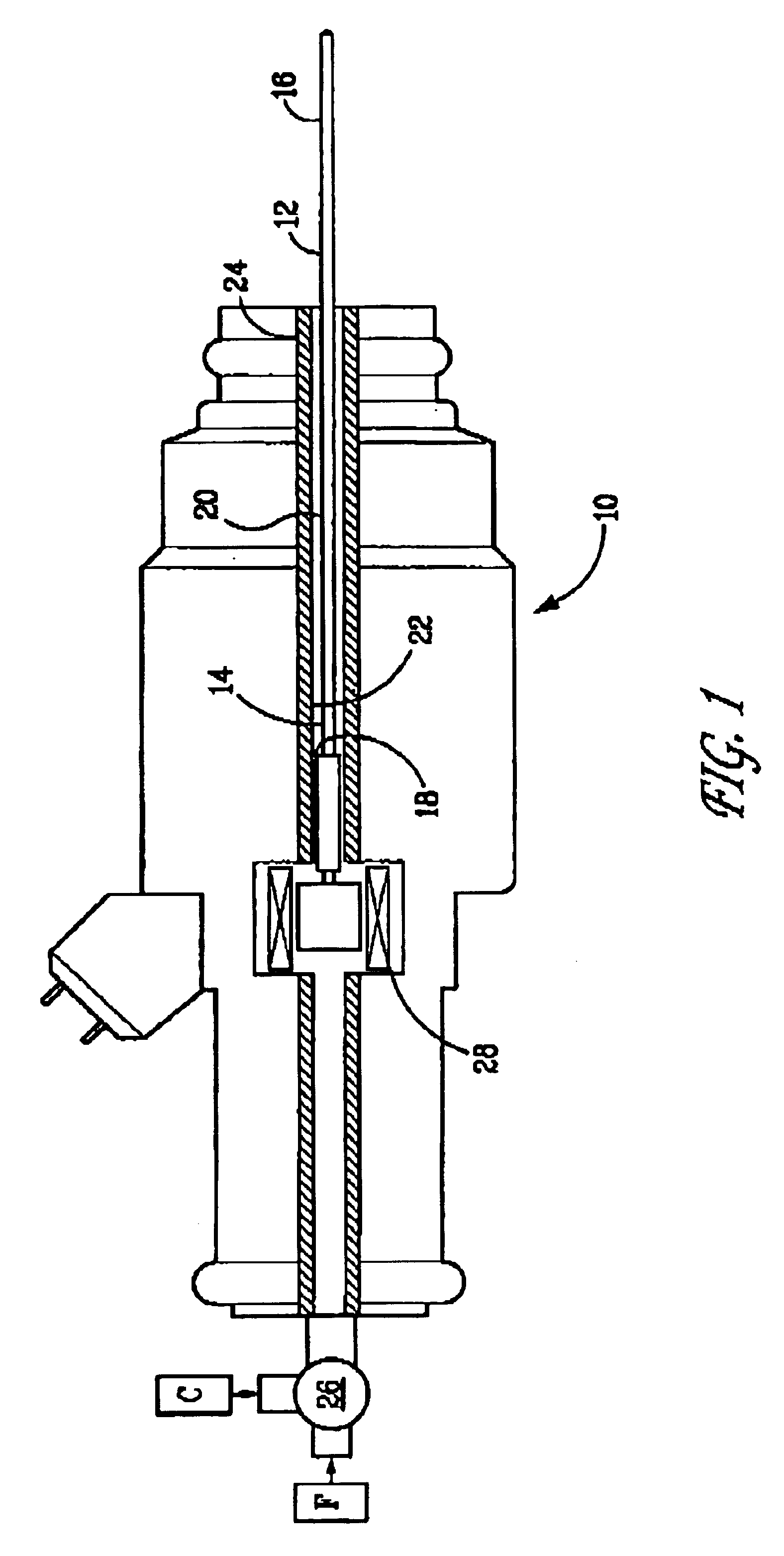
Tests were performed wherein JP 8 jet fuel was vaporized by supplying the fuel to a heated capillary passage at constant pressure with a micro-diaphragm pump system. In these tests, capillary tubes of different diameters and lengths were used. The tubes were constructed of 304 stainless steel having lengths of 1 to 3 inches and internal diameters (ID) and outer diameters (OD), in inches, as follows: 0.010 ID / 0.018 OD, 0.013 ID / 0.033 OD, and 0.017 ID / 0.025 OD. Heat for vaporizing the liquid fuel was generated by passing electrical current through a portion of the metal tube. The droplet size distribution was measured using a Spray-Tech laser diffraction system manufactured by Malvern. Droplets having a Sauter Mean Diameter (SMD) of between 1.7 and 4.0 μm were produced. SMD is the diameter of a droplet whose surface-to-volume ratio is equal to that of the entire spray and relates to the spray's mass transfer characteristics.

example 2

Tests were conducted to demonstrate the benefits of the oxidation cleaning technique on a heated capillary flow passage using an unadditized, sulfur-free base gasoline known to produce high levels of deposit formation. The capillary flow passage employed for these tests was a two-inch long heated capillary tube constructed of stainless steel, having an inner diameter of 0.023 inch. Fuel pressure was maintained at 10 psig. Power was supplied to the capillary to achieve various levels of R / Ro; where R is the heated capillary resistance and Ro is the capillary resistance under ambient conditions.

FIG. 8 presents a graph of fuel flow rate vs. time. As shown, for this gasoline containing no detergent additive, significant clogging was experienced in a very short period of time, with a 50% loss in flow rate observed in as little as 10 minutes.

After substantial clogging was experienced, fuel flow was discontinued and air at 10 psig substituted. Heating was provided during this period and, i...

example 3

This example demonstrates that clogging is far less severe in the heated capillary flow passage of Example 2, when a commercial-grade gasoline employing an effective additive package is employed. As shown in FIG. 9, less than a 10% reduction in fuel flow rate was experienced after running the device for nearly four hours.


PUM


Abstract

A method and apparatus for vaporizing liquid fuel. The apparatus includes at least one capillary flow passage, the at least one capillary flow passage having an inlet end and an outlet end; a fluid control valve for placing the inlet end of the at least one capillary flow passage in fluid communication with the liquid fuel source and introducing the liquid fuel in a substantially liquid state; a heat source arranged along the at least one capillary flow passage, the heat source operable to heat the liquid fuel in the at least one capillary flow passage to a level sufficient to change at least a portion thereof from the liquid state to a vapor state and deliver a stream of substantially vaporized fuel from the outlet end of the at least one capillary flow passage; and means for cleaning deposits formed during operation of the apparatus. The flow passage can be a capillary tube heated by a resistance heater or a section of a tube heated by passing electrical energy therethrough. The liquid fuel can be supplied to the flow passage at any desired pressure depending on the required mass flow rate for the application. The vaporized fuel can be mixed with air to form an aerosol having a mean droplet size of 25 μm or less to minimize ignition energy of the fuel-air mixture, promote fuel flow in an air stream, and combust the liquid fuel efficiently and cleanly.

Description

FIELDThe present invention relates to the preparation and delivery of fuel. More particularly, a method and apparatus according to the invention provides at least one heated capillary flow passage for vaporizing fuel.BACKGROUNDThe ability to produce finely atomized fluid sprays benefits many diverse applications including the manufacture of substrates for industry, the fueling of combustion systems, including the fueling of internal and external combustion engines, the formation of uniform-sized particles for the production of pharmaceutical products, the production of small particles for use as test standards and various applications in the electronics industry, in which thin-film deposition techniques are often employed to form resistors, capacitors and other components.In general, the completeness and cleanliness of liquid fuel combustion depends upon the fuel / air ratio, the combustion chamber mechanical and aerodynamic design, the fuel type, the fuel injector design and the fuel...

Claims


Application Information

Patent Timeline
Patent Type & Authority Patents(United States)
IPC IPC(8): F02M65/00F02M53/06F02M53/00F02M53/02F02M31/125F02M31/02F02M31/18F23D11/38F23D11/36F23D11/44F02M47/04F02M51/06F02M51/08F02M63/00F02M69/00
CPCF02M31/125F02M31/18F02M53/02F02M53/06F23D11/386F23D11/448F02M65/008Y02T10/126F23D2900/00002Y02T10/12F02M57/00F02B77/04F02M21/06
Inventor PELLIZZARI, ROBERTO O.
Owner PHILIP MORRIS USA INC
Why Eureka
Try Eureka