
Apparatus for endothermic reactions of organic compounds

an endothermic reaction and apparatus technology, applied in lighting and heating apparatus, physical/chemical process catalysts, furnaces, etc., can solve the problems of large investment capital requirements and operating costs associated with such endothermic processes, poor selectivity, and process usually end up limited in conversion

Inactive Publication Date: 2005-03-29
SUNOCO INC (R&M)
View PDF8 Cites 5 Cited by
  • Summary
  • Abstract
  • Description
  • Claims
  • Application Information

AI Technical Summary

Benefits of technology

The process of the invention has advantages over prior art processes for conducting endothermic reactions in that the process of the invention conducts the endothermic reaction in the same reaction zone in which an exothermic oxidation of hydrogen is conducted. Where the process of the invention is a dehydrogenation process, it has the advantages, as compared with the process of Imai above, of less explosion hazard, greater selectivity for oxidation of only the hydrogen component rather than the hydrocarbon component, and elimination of dilutes to control combustion of organics; and the advantages as compared with Clark above, of providing improved reactor design which efficiently uses the exotherm associated with hydrogen oxidation. The invention also provides novel processes using particular selective hydrogen oxidizing agents.

Problems solved by technology

The large investment capital requirements and operating costs associated with such endothermic processes are often related to poor selectivity and low conversion typical of those processes, or to the heat requirements of the processes.
Such processes are usually ultimately limited in conversion by an unfavorable position of equilibrium.
Some of the commercially used endothermic processes of the prior art use adiabatic reactors, with the resulting disadvantage that the requisite reactor size to approach equilibrium conversion becomes quite large due, to the rapid deceleration of the reaction as the reaction mixture progresses through the bed of catalyst and the temperature drops with increasing conversion of the reaction mixture.
However, a practical problem associated with endothermic processes which are conducted in the presence of oxygen in order to oxidize: product hydrogen in situ is that introduction of oxygen which has not been previously diluted with inert gas into the reactor may cause the production of oxygen-fuel mixtures within the bounds of the combustion envelope at temperatures above the autoignition temperature.
This may lead to unselective combustion of desired hydrocarbon products or to explosion in an extreme case.
To mix oxygen with hydrocarbons safely in a packed bed requires a large expense.
This design ameliorates the safety concerns but introduces a heat transfer problem.
This is a problem common to all the commercial dehydrogenation processes which use a packed bed reactor for dehydrogenation and not just those which rely on in situ hydrogen combustion to provide heat.
But even if hydrogen is oxidized in situ to make the overall process thermoneutral, unless the exothermic combustion process can be conducted in the same zone as the endothermic dehydrogenation, heat transfer limitations may limit efficiency.
Imai in U.S. Pat. Nos. 4,435,607 and 4,788,371 discloses dehydrogenation of alkanes in processes which include selective hydrogen combustion by oxygen, but have the disadvantage of adding oxygen to a zone in which there is either a high concentration of combustible organic compounds necessitating a high concentration of diluent such as steam to prevent combustion of organic compounds.

Method used


Image

  • Apparatus for endothermic reactions of organic compounds
  • Apparatus for endothermic reactions of organic compounds

Examples


Embodiment Construction

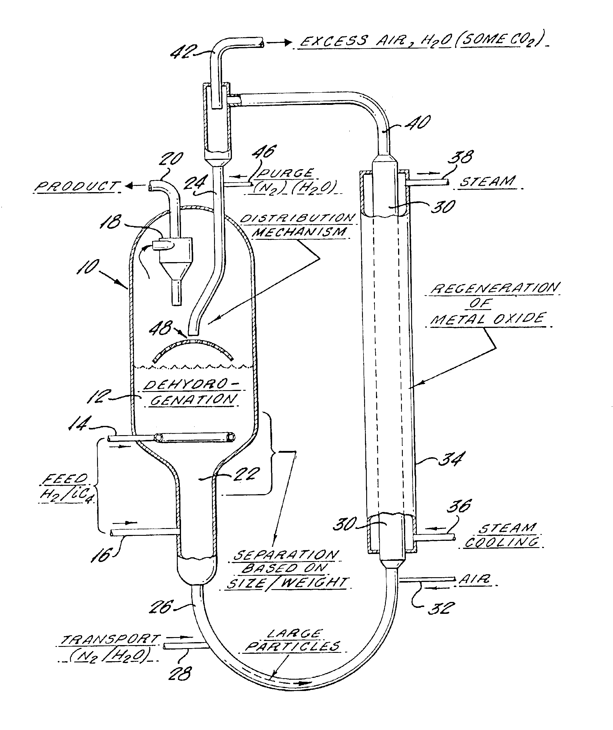
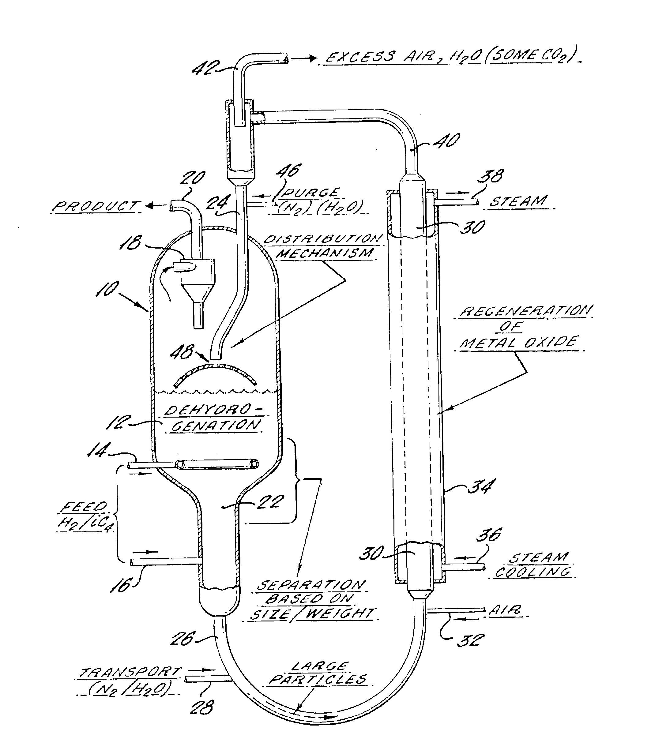
The process according to the invention is a process for conducting an endothermic reaction of a liquid or vaporous organic compound in the presence of molecular hydrogen and of multicomponent solids including a solid catalyst for the endothermic reaction and a hydrogen oxidizing solid reagent to react with the hydrogen. The solid catalyst and the hydrogen oxidizing solid reagent are intermixed, either as separate particles or incorporated within the same particle. The organic compound and the hydrogen are contacted with the catalyst and the hydrogen oxidizing reagent under conditions to produce organic products of the endothermic reaction and to react hydrogen by an exothermic reaction with the hydrogen oxidizing reagent to form deactivated hydrogen oxidizing reagent and water vapor. The deactivated hydrogen oxidizing reagent is reactivated by contact with an oxidizing agent in the absence of substantial quantities of hydrogen and in the absence of substantial quantities of organic ...


PUM

PropertyMeasurementUnit
pressureaaaaaaaaaa
temperatureaaaaaaaaaa
average particle sizeaaaaaaaaaa

Abstract

An apparatus for conducting an endothermic reaction of an organic' compound in the presence of molecular hydrogen and of multicomponent solids is described. The process of operating the apparatus comprises contacting the compound with a solid catalyst for the endothermic reaction and a hydrogen oxidizing solid reagent intermixed with the solid catalyst. Organic products of the endothermic reaction are produced, with evolution of molecular hydrogen. The solid catalyst becomes gradually deactivated by formation of carbonaceous deposits thereon. The evolved hydrogen undergoes an exothermic reaction with the hydrogen oxidizing solid reagent to form a reduction product which comprises deactivated hydrogen oxidizing solid reagent. The deactivated solid catalyst is reactivated by combustion of carbonaceous deposits thereon and the deactivated hydrogen oxidizing solid reagent is reactivated by contacting the reagent with an oxidizing agent in the absence of substantial quantities of hydrogen and in the absence of substantial quantities of organic compounds other than those on the surface of the reagent. The apparatus provides an endothermic reaction which is carried out in the presence of a fluidized bed of catalyst and in the presence of particles of granular hydrogen oxidizing solid reagent which move downwardly through the fluidized catalyst bed, and in which the solid catalyst and solid reagent are separated prior to reactivation thereof in separate reactivation zones.

Description

BACKGROUND AND PRIOR ARTEndothermic chemical conversions of hydrocarbons and other reactants have been extensively practiced in the prior art. The large investment capital requirements and operating costs associated with such endothermic processes are often related to poor selectivity and low conversion typical of those processes, or to the heat requirements of the processes. Such processes are usually ultimately limited in conversion by an unfavorable position of equilibrium. It is desirable therefore to favorably change the equilibrium by continuous removal of one of the reaction products, and to provide heat required for the process by the conduct of an exothermic reaction simultaneously with the endothermic reaction within the same reactor train. The present invention provides a selective process with improved conversion and consequent lower installation and operating costs while also providing major benefits associated with in situ heat generation and equilibrium shift to achie...

Claims


Application Information

Patent Timeline
Patent Type & Authority Patents(United States)
IPC IPC(8): B01J8/04B01J27/14B01J23/755B01J27/18C07C5/333C07C5/00C07B35/00C07B35/04
CPCB01J8/0453B01J23/755B01J23/866B01J27/1813B01J27/1815B01J29/24B01J29/63C07C5/3335B01J37/0207C07B35/04C07C11/08B01J2208/00274Y02P20/584
Inventor BIERL, THOMAS W.DURANTE, VINCENT A.FINKEL, LAWRENCE H.RESASCO, DANIEL E.
Owner SUNOCO INC (R&M)
Learn More