Method for the reformation of fuels, in particular heating oil
- Summary
- Abstract
- Description
- Claims
- Application Information
AI Technical Summary
Benefits of technology
Problems solved by technology
Method used
Image
Examples
second embodiment
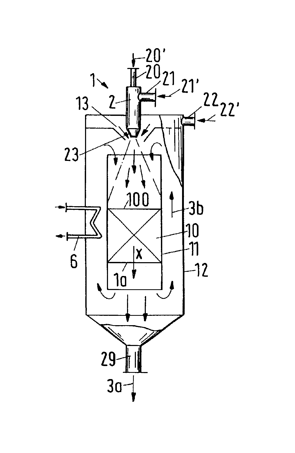
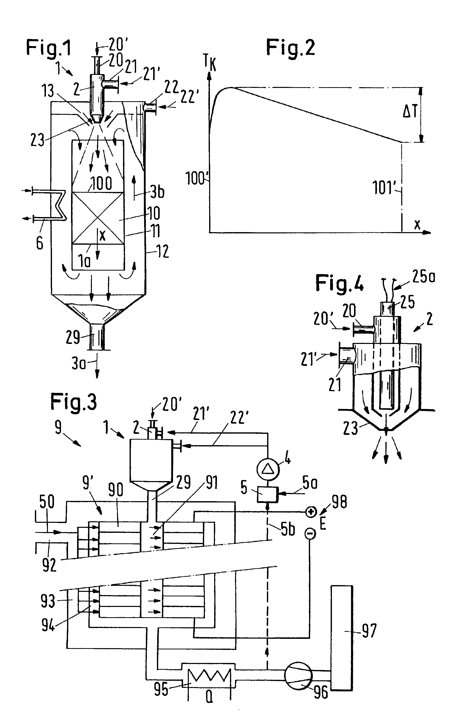
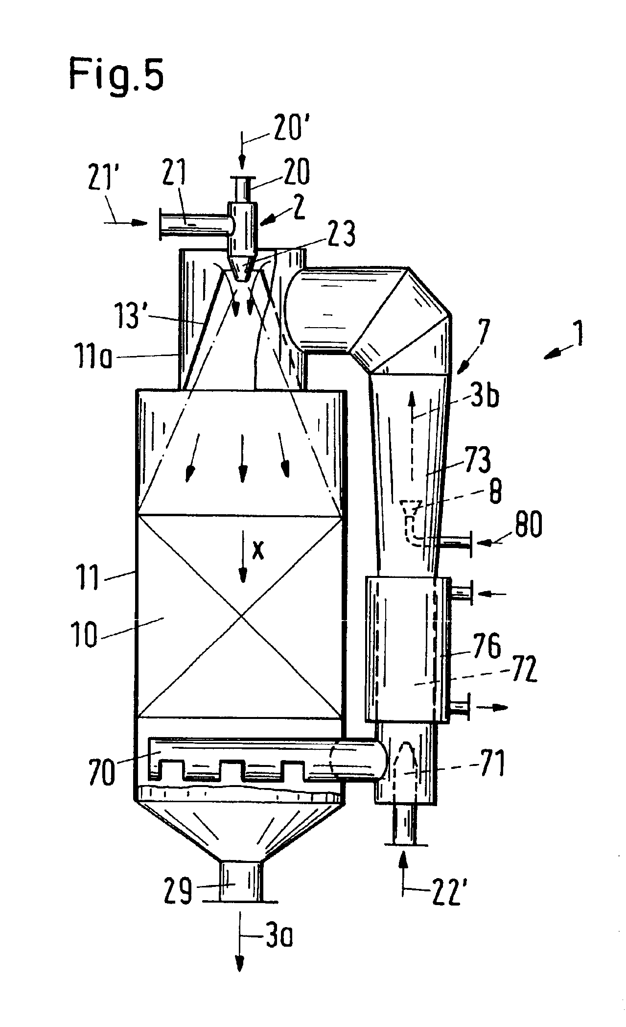
the apparatus of the invention is shown in FIG. 5. For the return flow 3b a second tube 7 is added to the first tube 11 containing the catalytic converter 10, with the second tube 7 being formed as a jet compressor. The second part flow 22′ and the oxygen containing gas are exploited as a driving medium. Synthesized gas is sucked in through a tube 70 by a driving nozzle 71. A subsequent downstream tube element 72, in which a momentum transfer takes place from the driving medium to the synthesized gas, is formed as a heat exchanger 76 which corresponds to the heat exchanger 6 in the embodiment of FIG. 1. In a subsequent diffuser 73, deionized water 80 can be sprayed by a nozzle 8 into the return flow 3b in order to utilize this fed-in water 80 as a reaction component of the reformation processes and for a cooling of the returned synthesized gas. The return flow 3b conveyed by means of the jet compressor 7 is distributed in the upper part of the apparatus 1 between an outer wall 11a a...
PUM
| Property | Measurement | Unit |
|---|---|---|
| Flow rate | aaaaa | aaaaa |
| Electrical resistance | aaaaa | aaaaa |
| Energy | aaaaa | aaaaa |
Abstract
Description
Claims
Application Information
 - R&D
- Intellectual Property
- Life Sciences
- Materials
- Tech Scout
- Unparalleled Data Quality
- Higher Quality Content
- 60% Fewer Hallucinations
Browse by: Latest US Patents, China's latest patents, Technical Efficacy Thesaurus, Application Domain, Technology Topic, Popular Technical Reports.
© 2025 PatSnap. All rights reserved.Legal|Privacy policy|Modern Slavery Act Transparency Statement|Sitemap|About US| Contact US: help@patsnap.com


