

Method of manufacturing a rigid internal gear of a wave gear device
a technology of wave gear and internal gear, which is applied in the direction of gear teeth, manufacturing tools, gearing, etc., can solve the problems of loss of the advantages of a wave gear device being lightweight, device becomes considerably heavy, and the rigid internal gear accounts for a large proportion of the weight of the components of the wave gear device, so as to achieve accurate formation and increase the bonding strength of the rings
- Summary
- Abstract
- Description
- Claims
- Application Information
AI Technical Summary
Benefits of technology
Problems solved by technology
Method used
Image

Examples
first embodiment
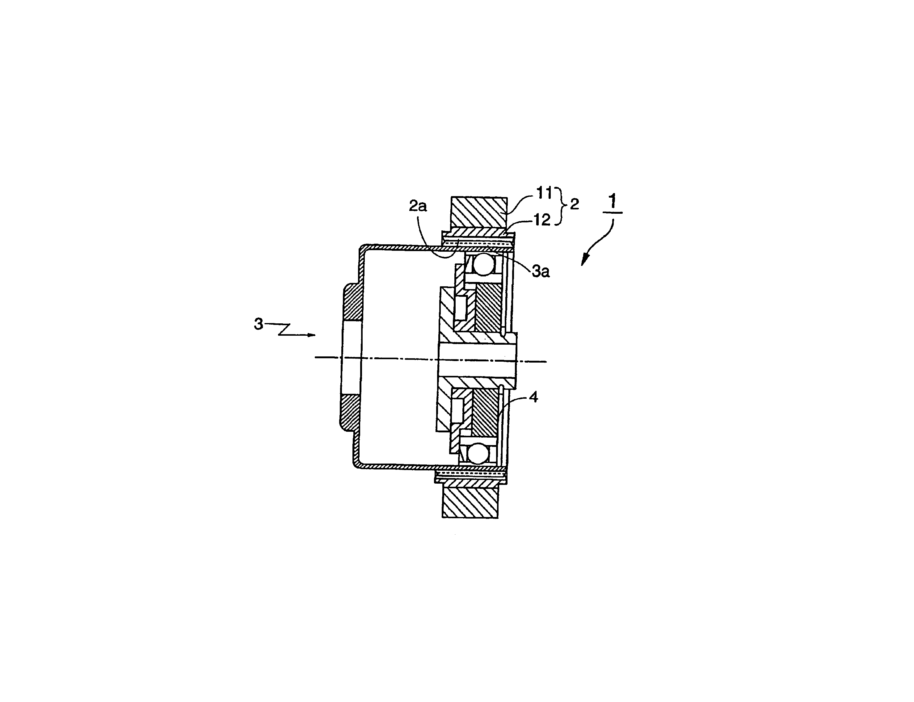
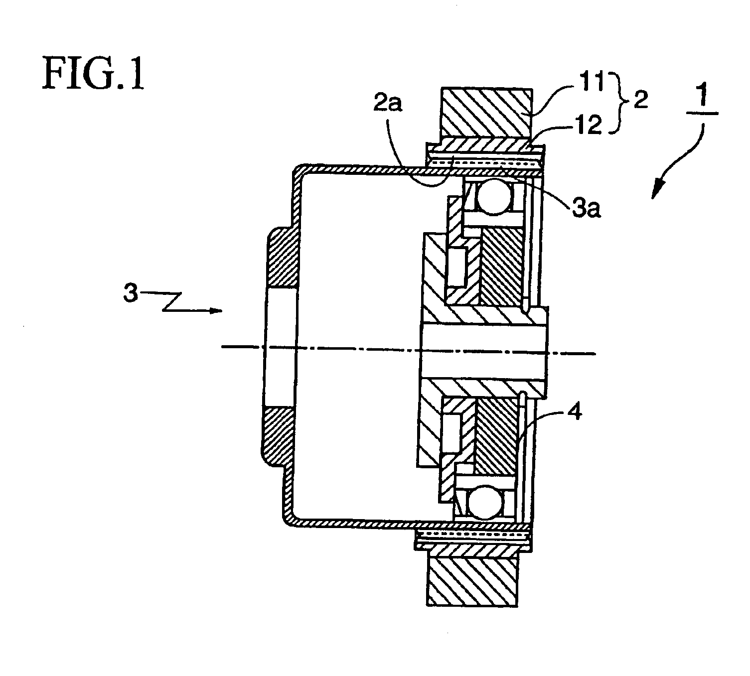
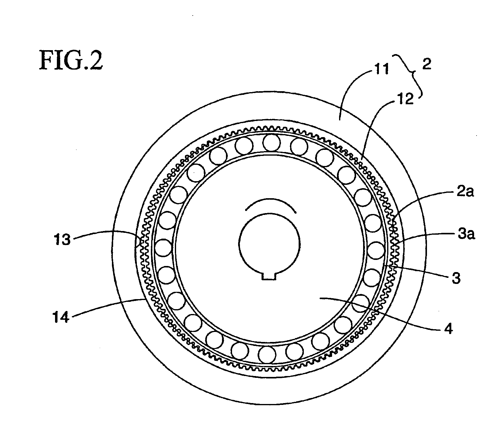
FIG. 1 is a schematic sectional view showing a wave gear device of the present embodiment, while FIG. 2 is a schematic front view of this wave gear device. As shown in these drawings, the wave gear device 1 of the present embodiment is composed of a circular rigid internal gear 2, a cup-shaped flexible external gear 3 disposed inside the rigid internal gear 2, and a wave generator 4 fitted into the flexible external gear 3. The wave generator 4 has an elliptical outline and flexes the flexible external gear 3 into an elliptical shape, so that external teeth 3a partially engage internal teeth 2a at both ends of the major axis of the elliptical shape. When the wave generator 4 is rotated by a high-speed rotational driving device such as a motor, the engaging portions of the gears 2 and 3 move in a circumferential direction. The difference in the number of teeth between the gears 2 and 3 is usually set at two, with this difference causing a relative rotation of the gears 2 and 3. Usual...
second embodiment
The following describes a different method for attaching the tooth-forming ring 12 and the main gear ring 11.
FIG. 4 is a general flowchart showing the manufacturing process of a composite rigid internal gear 2A of the present embodiment. As shown in the drawing, a tooth-forming ring 12 in which the internal teeth 2a have not been formed and a main gear ring 11 are separately manufactured (steps ST11, ST12). In the present embodiment, the tooth-forming ring 12 is formed of an abrasion-resistant and strong material, while the main gear ring 11 is formed of a lightweight material. Also, the materials are chosen so that the linear expansion coefficient of the tooth-forming ring 12 is larger than that of the main gear ring 11. Example combinations of the material and linear expansion coefficient of the tooth-forming ring 12 and those of the main gear ring 11 are shown below.
Main gear ring 11 (linearTooth-forming ring 12 (linearexpansion coefficient)expansion coefficient)Titanium alloy (8...
third embodiment
The following describes a different method for attaching the tooth-forming ring and the main gear ring, with reference to FIGS. 6 and 7.
FIG. 6 is an explanatory view of part of an outer circumferential surface of the tooth-forming ring 12C used in the bonding method of the present embodiment, and FIG. 7 is a general flowchart showing the manufacturing process of a composite rigid internal gear 2C of the present embodiment. The following describes the manufacturing process of the combined rigid internal gear 2C of the present embodiment, with reference to these drawings.
First, a tooth-forming ring 12C in which the internal teeth 2a have not been formed is manufactured from a ferrous material that is strong and abrasion-resistant (step ST21 in FIG. 7). Also, the main gear ring 11C is manufactured from a lightweight aluminum alloy (step ST22 in FIG. 7).
Next, a knurling process is performed on the outer circumferential surface 14C of the tooth-forming ring 12C to form knurls 15C (step S...
PUM
| Property | Measurement | Unit |
|---|---|---|
| temperature | aaaaa | aaaaa |
| thickness | aaaaa | aaaaa |
| strength | aaaaa | aaaaa |
Abstract
Description
Claims
Application Information