Heat exchanger flow-through tube supports

Inactive Publication Date: 2005-04-05
EXXON RES & ENG CO
View PDF12 Cites 14 Cited by
  • Summary
  • Abstract
  • Description
  • Claims
  • Application Information

AI Technical Summary

Benefits of technology

In a preferred embodiment of the present invention, high velocity axial flow is used in order to eliminate dead zones and related fouling problems.
As will be recognized by one of skill in the art, and as will be explained in further detail below, the present invention provides many advantages including a significant reduction of flow-induced tube vibration that can lead to tube damage, thermal expansion problems and dead zones that promote rapid fouling. Furthermore, the present invention provides axial flow on the shell side thereby eliminating the presence of dead zones which cause fouling and which are typically contained within prior art heat exchangers.
Additionally, the heat exchanger design according to the present invention permits op

Problems solved by technology

While many improvements to the basic design available in the twentieth century have been made, there still exist tradeoffs and design problems associated with the inclusion of heat exchangers within commercial processes.
In particular, one of the most problematic aspects associated with the use of heat exchangers is the tendency toward fouling.
In the case of corrosion, the surfaces of the heat exchanger can become corroded as a result of the interaction between the process fluids and the materials used in the construction of the heat exchanger.
The situation is made even worse due to the fact that various fouling types can interact with each other to cause even more fouling.
Fouling can and does result in additional resistance with respect to the heat transfer and thus decreased performance with respect to heat transfer.
Fouling also causes an increased pressure drop in connection with the fluid flowing on the inside of the exchanger.
Unfortunately, however, baffles serve to increase the fouling problem because they create dead zones on the shell side of the exchanger.
Unfortunately, higher fluid velocities are generally unattainable on the shell side of conventional shell-and-

Method used


Image

  • Heat exchanger flow-through tube supports
  • Heat exchanger flow-through tube supports
  • Heat exchanger flow-through tube supports

Examples


first embodiment

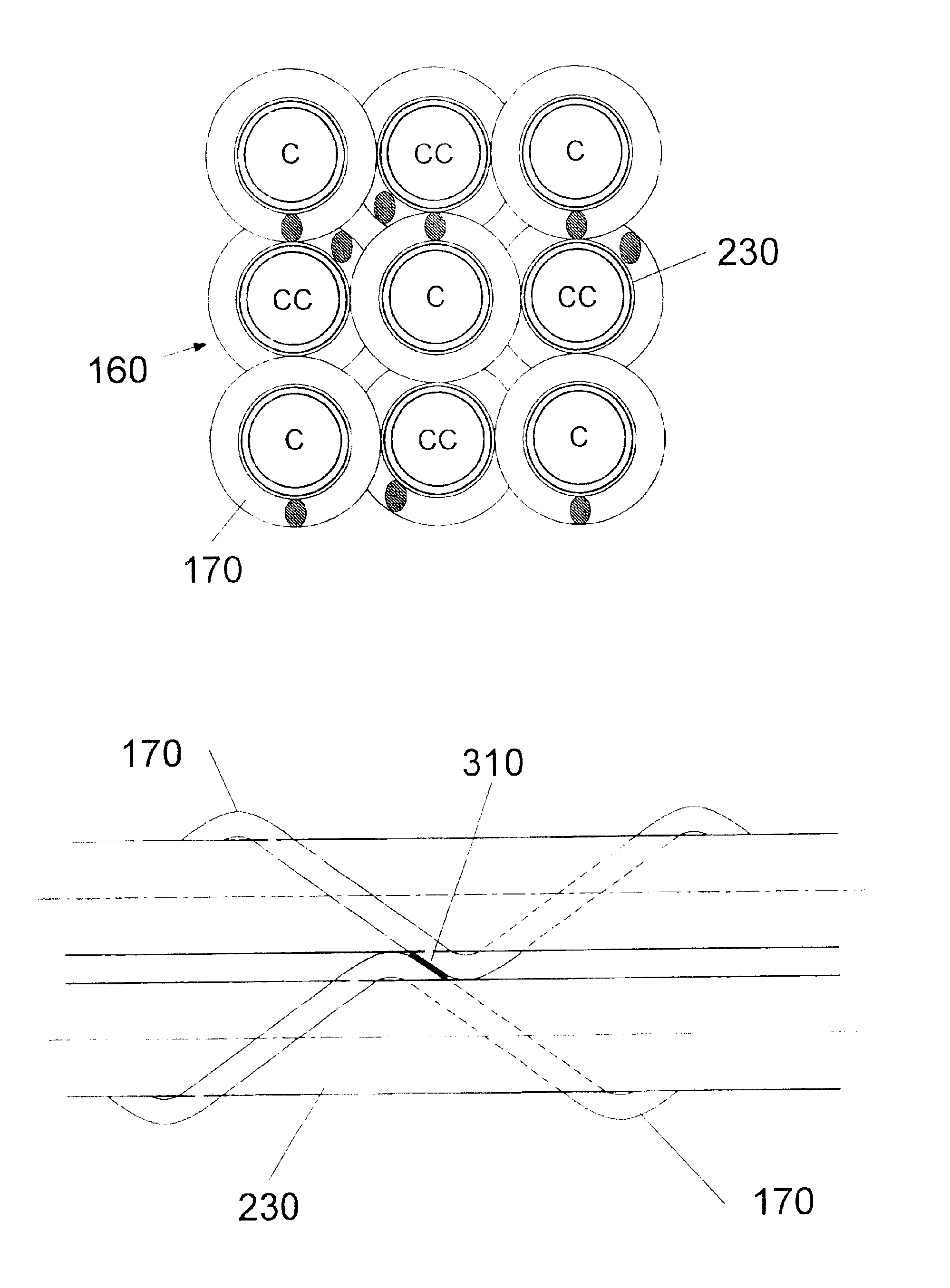
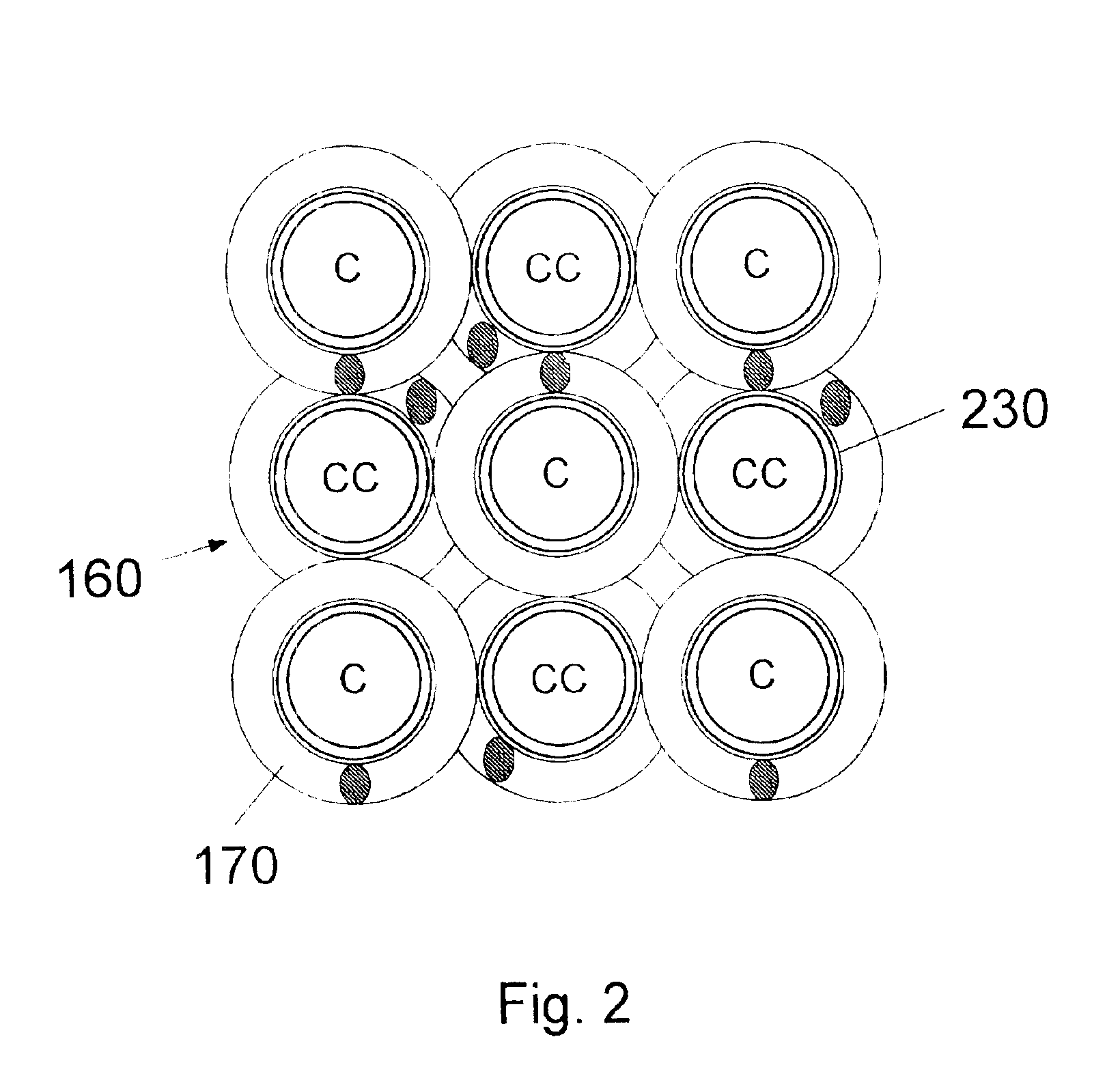
Turning now to FIG. 2, the novel support structure employed to support the tubes contained within tube bundle 160 is described. In a first embodiment as reflected by FIG. 2, coiled wires which have a diameter that is substantially equal to the space between the tubes comprising tube bundle 160 are used. The wire material is preferably comprised of erosion-resistant material such as stainless steel, titanium or other materials with similar metallurgical characteristics. In connection with the description herein, it will be understood by one of skill in the art that the term “wire” may encompass any or all of a wire, rod, strip or bar, all of which may be implemented in constructing the support structure of the present invention. As can be seen in FIG. 2, in the finished product, the wire material is wrapped around the tubes 230 to form coils that overlap with one another.

The coils structure is preferably constructed as follows. Coils 170 are prefabricated according to the specified d...

second embodiment

FIG. 5 illustrates the trimming requirements which may be undertaken in any embodiment of the present invention wherein the coil thickness is equal to any amount greater than one-half of the inter-tube spacing amount (i.e. any embodiment other than the above-described second embodiment). In such cases, it is possible to trim coil wire 510 so that it may make planar contact with its neighboring coil wire, for example in FIG. 5, coil wire 520. By employing trimming, and thus providing planar contact between coil wires 510 and 520, it is possible to create a larger contact area and thus provide a stronger weld. According to the teachings of the present invention, coil wires should be trimmed down to approximately one-half of the inter-tube space. For example, if the coil thickness of coil wires 510 and 520 were 70% of the inter-tube space, each of coil wires 510 and 520 should be trimmed down to approximately 50% of the inter-tube space at the contact point at weld 530.

third embodiment

FIG. 6 is an end view of the present invention wherein the tubes 610 are arranged in triangular pitch. According to the teachings of the present invention, in this case, some tubes 610 will be contained within the interior of coils 620 and others will not. The tubes 610 that are not contained within the interior of individual coils 620 are nonetheless supported by the exterior of the coils 620 which are adjacent to the relevant tube 610. Again, in this embodiment, it is preferable that coils which are adjacent to one another be wound in opposite directions (i.e. clockwise adjacent to counterclockwise).

In FIG. 6, the coil thickness is equal to the inter-tube spacing which results in an overlap as between the adjacent coils when viewed from the end as in the FIG. 6 view. Alternatively, but not shown, coil thickness in the triangular pitch case can be anywhere from 50% of inter-tube spacing to 100% of inter-tube spacing. As discussed above, in the case of 50% of inter-tube spacing, the...


PUM


Abstract

The present invention comprises a novel tube support system for a heat exchanger that serves to replace the baffles present in typical shell-and-tube heat exchangers. The shell-and-tube heat exchanger of the present invention employs helically coiled wires to form a support structure for the tubes contained within the heat exchanger shell. The elimination of baffles and the use of the coil support structure according to the present invention permits axial fluid flow for the shell side fluid and significantly minimizes fouling problems and tube damage resulting from flow-induced tube vibration.

Description

BACKGROUND1. Field of the InventionThe present invention relates generally to heat exchangers and more particularly to support structures for heat exchanger tubes within heat exchanger devices.2. Background of the InventionAlthough heat exchangers were developed many decades ago, they continue to be extremely useful in many applications requiring heat transfer. While many improvements to the basic design available in the twentieth century have been made, there still exist tradeoffs and design problems associated with the inclusion of heat exchangers within commercial processes.In particular, one of the most problematic aspects associated with the use of heat exchangers is the tendency toward fouling. Fouling refers to the various deposits and coatings which form on the surfaces of heat exchangers as a result of process fluid flow and heat transfer. There are various types of fouling including corrosion, mineral deposits, polymerization, crystallization, coking, sedimentation and bio...

Claims


Application Information

Patent Timeline
IPC IPC(8): F28F9/013F28F9/007F28D7/16
CPCF28F9/0137
Inventor WANNI, AMAR S.CALANOG, MARCIANO M.
Owner EXXON RES & ENG CO
Why Eureka
Try Eureka