Edge trimming tape and method of manufacture

a technology of cutting tape and manufacturing method, applied in the direction of thin material processing, coating, pretreatment surface, etc., to achieve the effect of simple and cost-effectiv

Inactive Publication Date: 2005-04-05
LANGEMAN MFG
View PDF12 Cites 18 Cited by
  • Summary
  • Abstract
  • Description
  • Claims
  • Application Information

AI Technical Summary

Benefits of technology

The present invention provides a simple and cost-effective method for cutting the protective layer without in any way damaging the underlying area or underlying surface which is intended to be protected.
The filament used to cut through the coating may vary depending on the force required to cut through the coating. A common music wire with a diameter as small as seven thousandths of an inch (0.007″) is adequate for cutting many polyurethane coatings up to a certain thickness and cure time. The masking materials commonly used in the painting and coating of motor vehicle bodies and other surfaces are capable of being applied to both curved and straight lines, to define the surface to be painted or coated. Similarly, the thin filament may be applied along the edge of a curved line to cut the coating material along a curve. A small steel wire size also makes it easy to form and adhere the filament to the surface as it is positioned around tight bends and curvatures. However, a disadvantage of the smaller wire is that it may break while pulling the wire through a thick coating or a harder coating with a high tear strength factor. In this case the filament could be a larger diameter wire size with a higher breaking strength while still maintaining as high a degree of flexibility as possible.
The present invention further provides a self-adhesive, filament-bearing tape which is particularly suited to carrying out the method of the present invention, and an apparatus which is adapted to easily and quickly manufacture the said self-adhesive tape.

Problems solved by technology

However, a disadvantage of the smaller wire is that it may break while pulling the wire through a thick coating or a harder coating with a high tear strength factor.

Method used


Image

  • Edge trimming tape and method of manufacture
  • Edge trimming tape and method of manufacture
  • Edge trimming tape and method of manufacture

Examples


Embodiment Construction

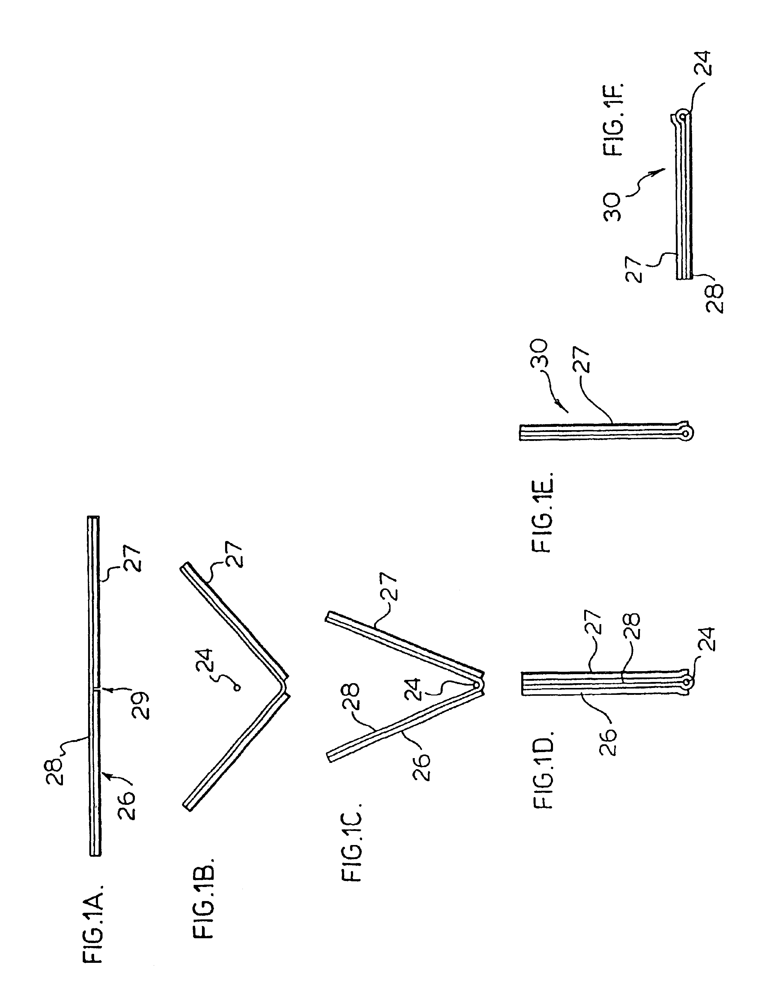
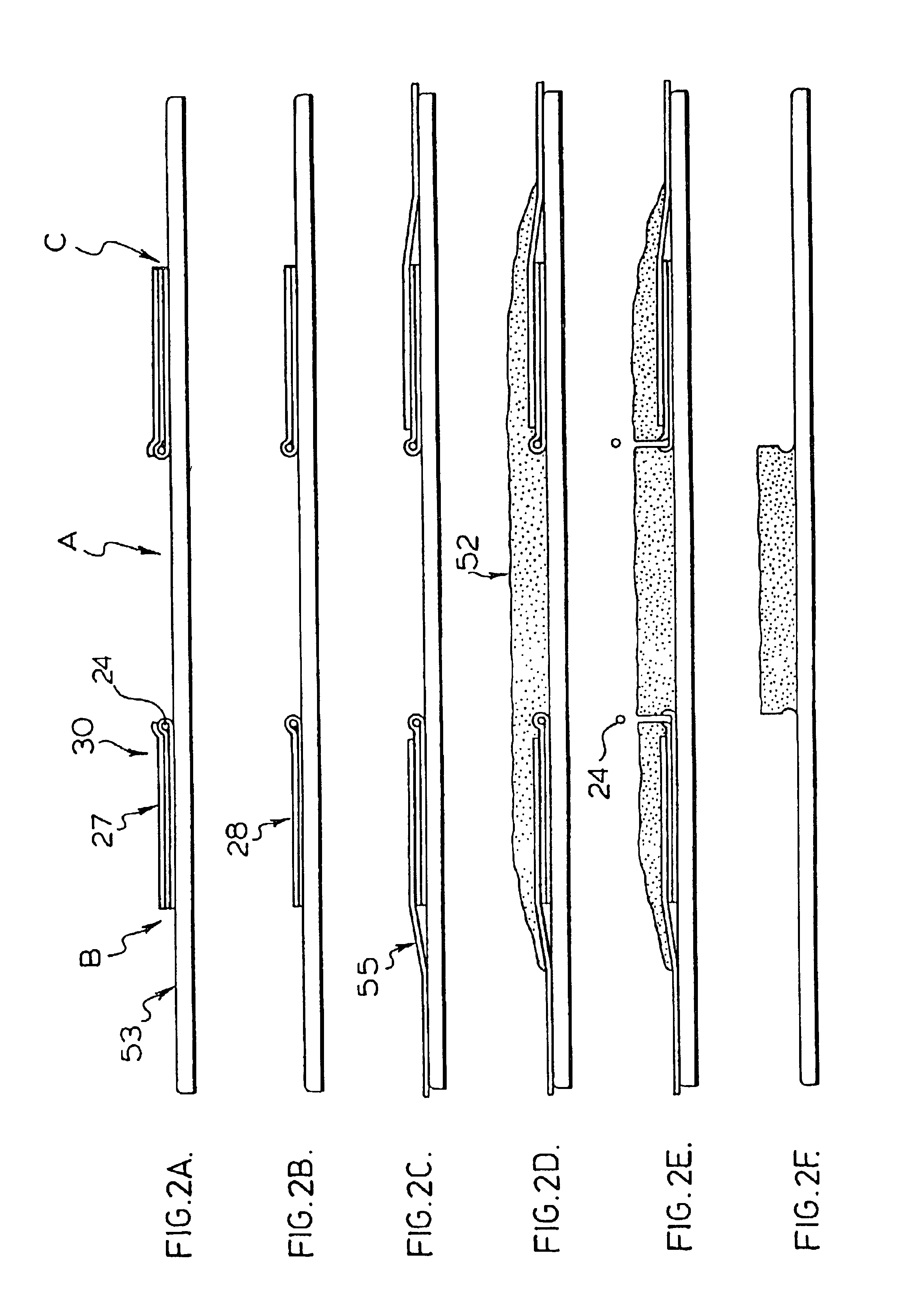
The method of the present invention may be more readily understood by referring to the attached drawings.

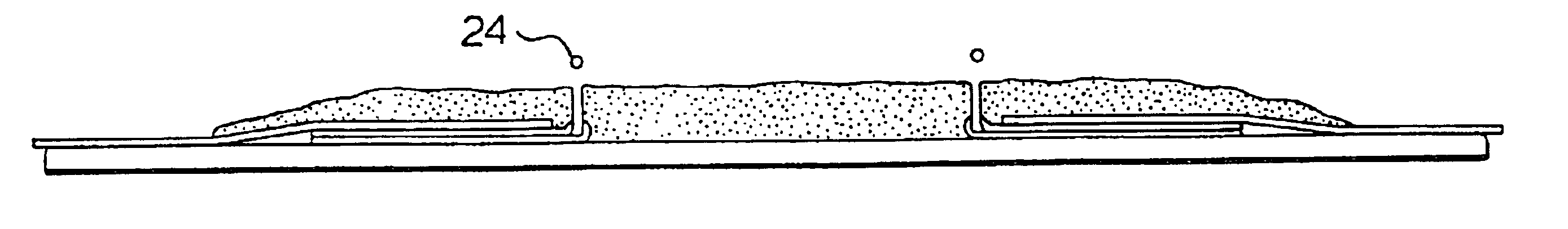
Referring first to FIGS. 1A-1F, there is shown a self-adhesive tape that is particularly suited to the application of the present invention. The tape 30, as shown in FIGS. 1A through 1F essentially comprises a folded adhesive layer 28, at the edge of which is a filament 24, retained in place by the adhesive layer 28. The adhesive layer may be a non-adhesive substrate coated with a conventional adhesive material, or may, in some circumstances, comprise a film of adhesive material.

As discussed in more detail below, the filament may be retained in place at the edge of the adhesive tape by folding the tape over die filament to envelope the filament within the adhesive tape, as shown in FIGS. 1A, 1B, 1C, and 1D. As further shown in FIGS. 1A, 1C and 1D, a layer of substrate of non-adhesive, easy-to-release material 26 and 27 may be applied to each of the adhesive surfaces of the self-a...


PUM

PropertyMeasurementUnit
diameteraaaaaaaaaa
adhesiveaaaaaaaaaa
tensile strengthaaaaaaaaaa

Abstract

The present invention provides an adhesive filament-bearing adhesive tape comprising an adhesive substrate adapted to be releasably adhered to a surface to be coated, and a filament releasably adhered to an edge of that substrate, that is useful in trimming a coating applied to a surface.The invention further provides a method of trimming a coating applied to a surface comprising applying to the surface to be coated a masking material to define the area to be coated and a filament of material of sufficient tensile strength to cut the coating material; applying coating material to the surface; allowing the coating material to dry or cure until it obtains sufficient strength to hold a cut edge; and drawing the filament through the coating to cut the coating.Finally, the present invention provides an apparatus for making a filament-bearing adhesive tape comprising means for folding an adhesive substrate along a predefined line; means for applying a filament to the interior of the fold so formed; and means for closing said fold to retain said filament at the edge of the filament bearing tape.

Description

TECHNICAL FIELDThe present invention relates to a method of trimming or cutting a coating material that may be applied to a relatively smooth surface, and is particularly useful for trimming or cutting a curable material such as polyurethane or paint without damaging the surface to which it is applied.BACKGROUND ARTIt has become increasingly common to apply a curable coating, such as a polyurethane, to an exposed surface such as a wall, floor or automobile body to offer protection against, for example, corrosion, moisture or abrasion. These coatings are often applied by spraying, rolling or painting the coating material on to the surface to be protected, and allowing the coating material to dry or cure in place.Some polyurethane coatings as well as other high strength coatings are available for application in the form of a single component formulation.Many commercially useful coating materials, such as paints, epoxies, varnishes, polyurethanes and other coating materials are availab...

Claims


Application Information

Patent Timeline
Patent Type & Authority Patents(United States)
IPC IPC(8): B05B15/04B05D1/32C09J7/02
CPCB05B15/0456B05D1/32Y10T428/24793Y10T428/24207Y10T428/149Y10T428/1476Y10T428/14Y10T428/24215Y10T428/1495B05B12/24
Inventor LANGEMAN, GARY D.
Owner LANGEMAN MFG
Why Eureka
Try Eureka