Method and apparatus for determining the rotational rate of a rotating device

a technology of rotating devices and rotational rate, which is applied in the direction of motor/generator/converter stoppers, dynamo-electric converter control, instruments, etc., can solve the problems of unnecessarily adding to the complexity and cost of motors, unfavorable inspection of the internal of the motor, and the inability of the motor shaft to be used for motor speed measurement, etc., to achieve the effect of preventing access to the interior of the motor, low cost cos

Inactive Publication Date: 2005-04-05
TRW AUTOMOTIVE US LLC
View PDF14 Cites 27 Cited by
  • Summary
  • Abstract
  • Description
  • Claims
  • Application Information

AI Technical Summary

Benefits of technology

It is contemplated that an EPHS system will utilize a totally encapsulated switched reluctance motor. Accordingly, the motor shaft is not accessible for motor speed measurements. Furthermore, the load on the motor will vary as steering commands are received. However, including a tachometer generator for testing purposes would unnecessarily add to motor complexity and cost. Additionally, access to the interior of the motor is prevented when the motor is encapsulated. Therefore, it would be desirable to provide a non-invasive apparatus and method for measuring motor speed and analyzing vibration sources.
While a known non-invasive method is described above that includes one or more Hall effect devices, the signals generated by the detection method are hard to detect upon the outside of a sealed device such as a motor used with a EPHS system. Furthermore, signals that are detected tend to be noisy, causing accuracy problems for the measurement. Accordingly, a non-invasive apparatus and method for measuring motor speed and analyzing vibration sources that also has a low cost and provides accurate data is desirable.

Problems solved by technology

Accordingly, the motor shaft is not accessible for motor speed measurements.
However, including a tachometer generator for testing purposes would unnecessarily add to motor complexity and cost.
While a known non-invasive method is described above that includes one or more Hall effect devices, the signals generated by the detection method are hard to detect upon the outside of a sealed device such as a motor used with a EPHS system.
Furthermore, signals that are detected tend to be noisy, causing accuracy problems for the measurement.

Method used


Image

  • Method and apparatus for determining the rotational rate of a rotating device
  • Method and apparatus for determining the rotational rate of a rotating device
  • Method and apparatus for determining the rotational rate of a rotating device

Examples


Embodiment Construction

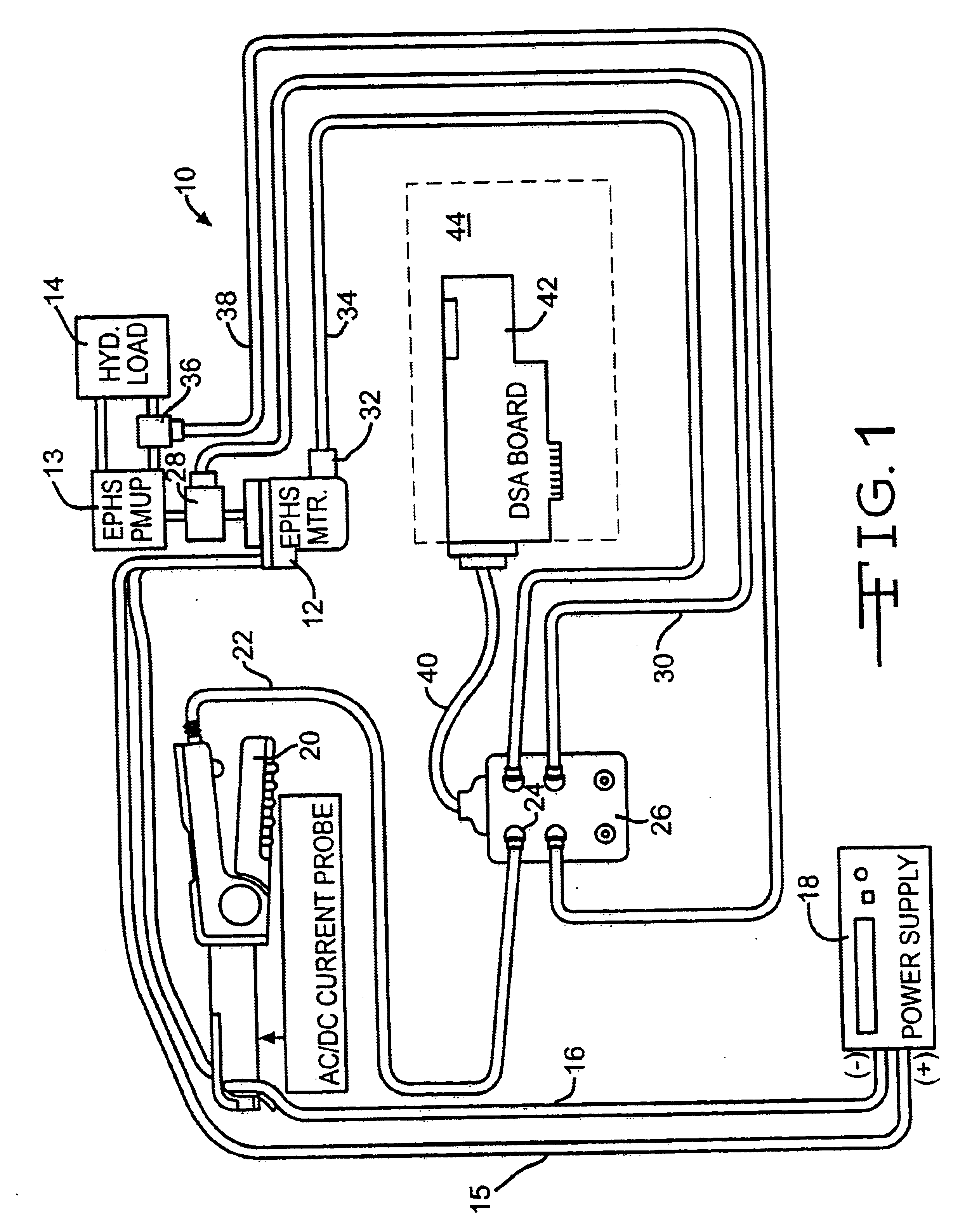
Referring now to the drawings, there is illustrated in FIG. 1 a schematic drawing of an apparatus 10 for measurement of the speed of a brushless switched reluctance DC motor 12 for an EPHS system. While the motor 12 utilized in the preferred embodiment is a switched reluctance motor, the apparatus also can be used with other types of electric motors. The motor 12 includes a control circuit that selectively energizes the motor stator windings (not shown) to generate a rotating magnetic field. The energization is accomplished by electronic switching of the DC voltage supplied to the motor. Accordingly, the motor current will fluctuate with the switching. As shown in FIG. 1, the motor shaft is mechanically connected to an EPHS pump 13 that provides a variable mechanical load to the motor 12. The motor includes a control circuit that senses the mechanical demand of the pump 13 and generates a rotating electric field to match the demand. The pump 13 also is connected to a hydraulic circu...


PUM


Abstract

A non-invasive apparatus and method for measuring the speed of a rotating device that includes a sensor that measures a dynamic characteristic of the rotating device. A sample of the signal is transformed from the time domain into a frequency spectrum. The frequency spectrum is then analyzed to determine the motor speed. The resulting motor speed can be combined with other motor data by an order analysis to identify malfunctioning or improperly installed components.

Description

BACKGROUND OF INVENTIONThis invention relates in general to rotating devices and in particular to a method and apparatus for measuring the rotational rate of a rotating device.Motor vehicles include an ever increasing number of electrical and electronic systems. Many such systems include components that can generate noise and vibration that can intrude into the vehicle passenger compartment and exceed the Noise, Vibration and Harshness (NVH) specifications for the vehicle. Anti-lock brake and vehicle stability systems include motor driven pumps and cyclically actuated solenoid valves that control application of pressurized brake fluid to wheel brake cylinders. A newer system being provided for vehicles is Electrically Powered Hydraulic Steering (EPHS), that utilizes a motor driven pump to provide hydraulic steering assistance. The EPHS system replaces the conventional hydraulic power steering system in which the power steering pump is mechanically belt driven by a pulley attached to...

Claims


Application Information

Patent Timeline
Patent Type & Authority Patents(United States)
IPC IPC(8): H02P1/00H02P1/04G01P3/44G01P3/48
CPCG01P3/48G01P3/44
Inventor JONES, MICHAEL A.
Owner TRW AUTOMOTIVE US LLC
Why Eureka
Try Eureka