Front end module

module technology, applied in the direction of printed circuit non-printed electric components association, multiple-port network, high-frequency circuit adaptation, etc., can solve the problems of difficult to provide good balance characteristics in saw filter used in higher frequency, difficult to provide good balance characteristics in saw filter used in high frequency, etc., to reduce the number of components and mounting area, easy to adjust, and easy to tailor a front end module. the effect of quick and easy adjustmen

Inactive Publication Date: 2005-04-05
TDK CORPARATION
View PDF14 Cites 19 Cited by
  • Summary
  • Abstract
  • Description
  • Claims
  • Application Information

AI Technical Summary

Benefits of technology

According to the invention, it is easy to adjust the output impedance of a front end module to the input impedance of a receiver circuit by changing the characteristics of a balun provided in the front end module. Matching between elements other than the balun is not required so that it is possible to tailor a front end module easily and promptly to a design change of a receiver circuit.
An impedance matching circuit between a SAW filter and a balun may be omitted by mounting/incorporating the balun on/in a front end module thus it is not necessary to externally provide matching components. This reduces the number of components and mounting area on a printed circuit boar...

Problems solved by technology

However, it is difficult to provide a good balance to obtain sufficient characteristics in a balanced SAW filter.
This is because a more minute pattern design is required as the frequency band u...

Method used


Image

  • Front end module
  • Front end module
  • Front end module

Examples


Embodiment Construction

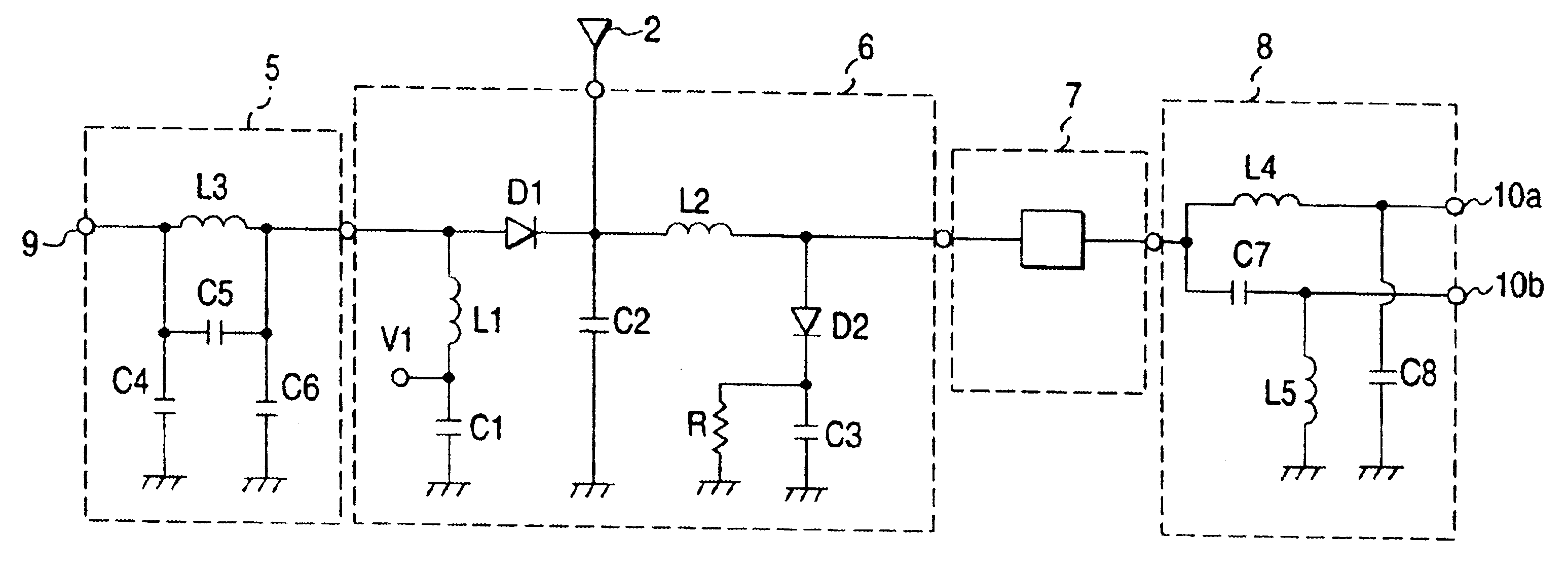
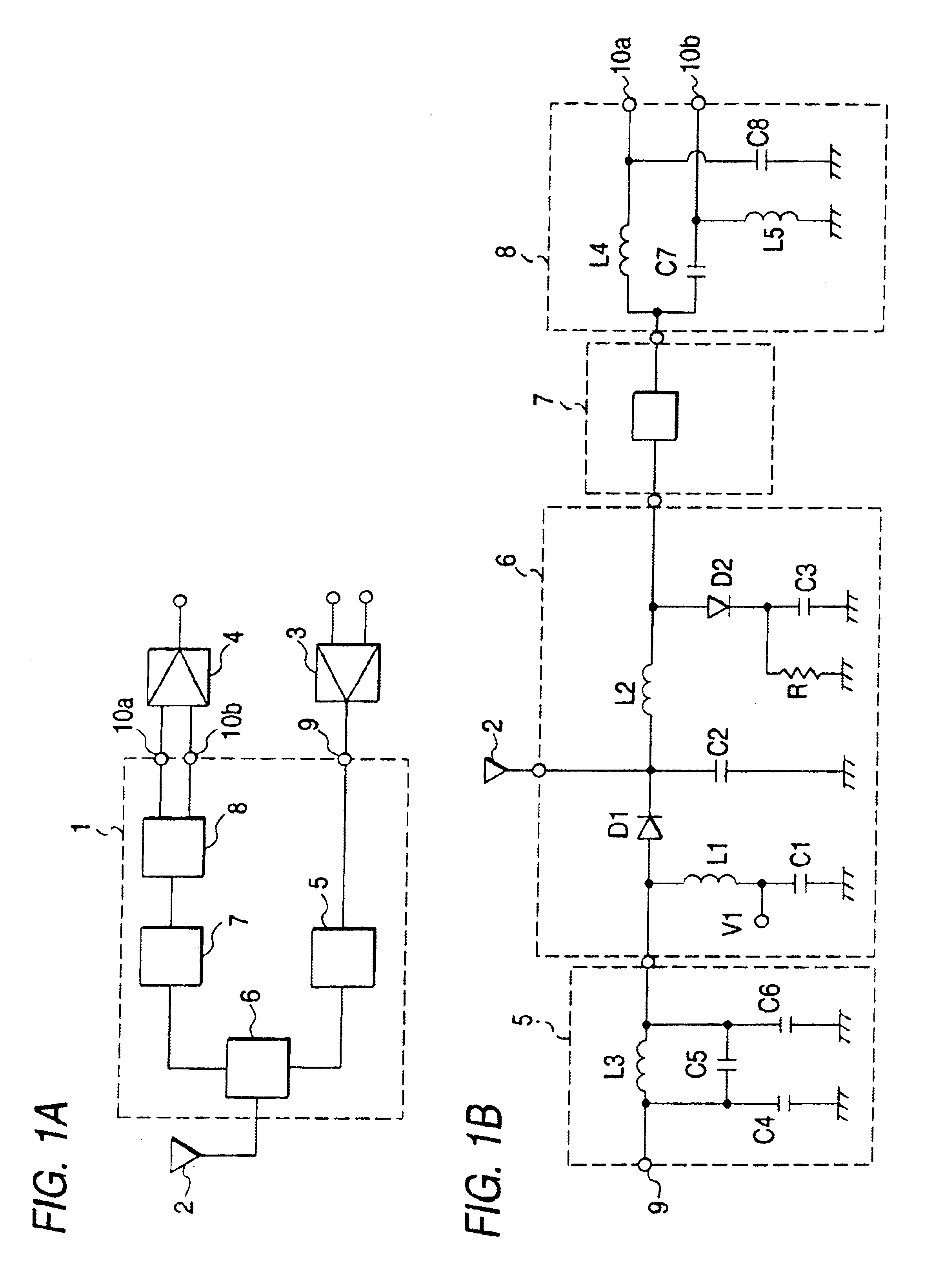
The embodiments of the invention will be described referring to drawings. FIG. 1A is a block diagram showing a front end module according to an embodiment of the invention. In FIG. 1A, a section 1 enclosed by dotted lines is a front end module, a numeral 2 represents an antenna, 3 represents an amplifier circuit in the transmitter circuit, 4 represents an amplifier circuit in the receiver circuit, 5 represents a low pass filter for removing harmonics generated in the amplifier circuit 3, 6 represents an antenna switch for selecting between transmission and reception, 7 represents a SAW filter provided as a band pass filter, and 8 represents a balun. A numeral 9 represents a port connected to the amplifier circuit 3 of the transmitter circuit, 10a and 10b represent ports connected to the amplifier circuit 4 of the receiver circuit.

FIG. 1B is a circuit diagram of the front end module 1. In the figure, numerals 5 through 9 , 10a, 10b are components shown in FIG. 1A. C1 through C8 repre...


PUM


Abstract

Such a front end module is arranged as a module using an antenna switch (6), a low pass filter (5), a surface acoustic wave filter (7) and a balun (8) integrated by a multilayer substrate (11) and components incorporated in or mounted on the multilayer substrate (11).

Description

BACKGROUND OF THE INVENTIONThe present invention relates to a front end module mainly including an antenna switch available to mobile communications apparatus such as a cell phone and an automobile phone.A high frequency circuit of related art mobile communications apparatus includes an antenna switch or selectively connecting an antenna to a transmitter circuit or a receiver circuit, a surface acoustic wave filter (hereinafter referred to as a SAW filter) as a band-pass filter for filtering a signal received via the antenna switch and an amplifier circuit for amplifying a received signal that has passed the filter.The internal circuit of an analog IC used in the amplifier circuit of a receiver circuit generally includes a differential amplifier circuit. The input terminal of an analog IC is usually of a balanced system for input a received signal as a potential difference between two terminals. Thus, it is desirable to use a balanced SAW filter as the SAW filter.However, it is diff...

Claims


Application Information

Patent Timeline
IPC IPC(8): H04B1/44H04B1/48H05K1/18H05K1/16H05K1/02H03H7/42H05K3/46H03H7/46H04B1/18H04B1/3822H04B1/40
CPCH03H7/463H04B1/48H05K1/181H05K1/16H05K1/0237H04B1/18
Inventor HARADA, NOBUMISUGA, SATOSHIIWATA, MASASHIHASEGAWA, HIDEKITADANOH, HIROSHI
Owner TDK CORPARATION
Why Eureka
Try Eureka