Tuning scheme for code division multiplex broadcasting system

a technology of code division and multiplex, applied in the field of satellite broadcasting techniques, can solve the problems of large time delay, inability to retransmit lost symbols or packets, and inability to retransmit lost symbols or packets, and achieve the effect of reducing delay

Inactive Publication Date: 2005-04-05
AVAGO TECH INT SALES PTE LTD
View PDF21 Cites 114 Cited by
  • Summary
  • Abstract
  • Description
  • Claims
  • Application Information

AI Technical Summary

Benefits of technology

According to one aspect of the invention, the CDM satellite transmission system provides a tuning channel corresponding to each program channel that reduces the delay when a mobile receiver is first tuned to a selected program channel. The tuning channel utilizes a shorter interleaver length, if any, than the corresponding primary program channel. As used herein, a “tuning channel” is a channel that transmits at least a portion of the corresponding prim

Problems solved by technology

In digital broadcasting applications, feedback or retransmission of lost symbols or packets are not desirable solutions, because of the nature of the broadcasting environment.
A large interleaver length, however, results in large time delays when first tuning the receiver to a broadcast program, since decoding and reproduction of the original program content can start only after an enti

Method used


Image

  • Tuning scheme for code division multiplex broadcasting system
  • Tuning scheme for code division multiplex broadcasting system
  • Tuning scheme for code division multiplex broadcasting system

Examples


Embodiment Construction

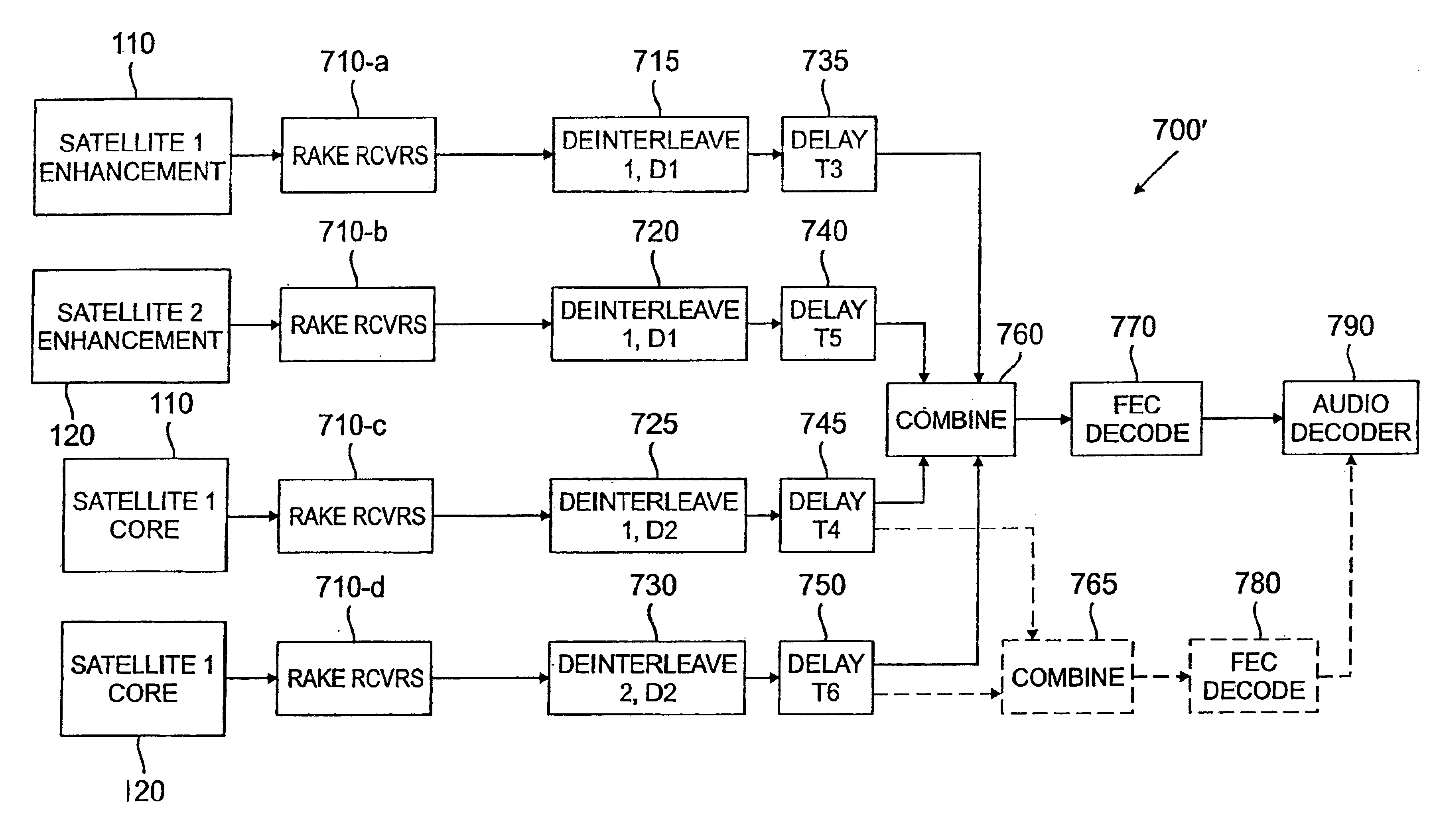
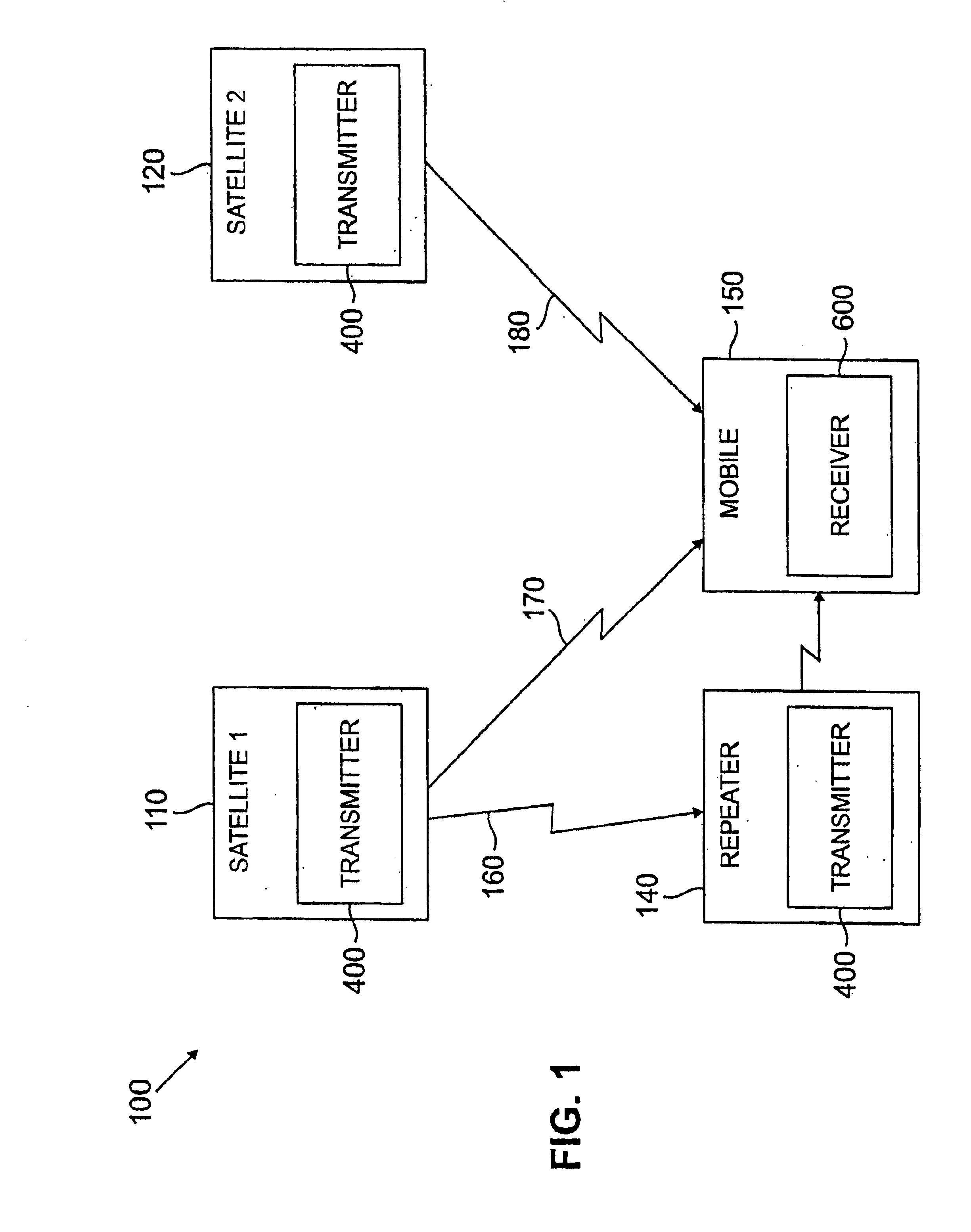
FIG. 1 illustrates a CDM satellite transmission system 100 in accordance with the present invention. The CDM satellite transmission system 100 transmits digital music and other audio information from an uplink station (not shown) to one or more mobile receivers, such as the mobile receiver 150. A plurality of audio channels are multiplexed onto a carrier frequency using Code Division Multiple Access technology. The term Code Division Multiplexing is used herein, since the satellite transmission system 100 operates in a broadcast mode. A maximum bit error rate of 10−5 is generally desirable for compact disk quality music.

As shown in FIG. 1, the illustrative CDM satellite transmission system 100 includes two satellites 110, 120 operating in a broadcast mode. The satellites 110, 120 are designed to be geo-synchronous, and are located over a desired geographical coverage area, such as over the eastern and western United States, at appropriate angles of elevation, as dictated by the requ...


PUM


Abstract

A CDM satellite transmission system is disclosed that broadcasts programming content, such as audio and video information, using one or more geo-synchronous satellites based on Code Division Multiple Access technology. Forward error correction coding and interleaving are used prior to broadcasting the signals over the CDM channel to account for signal loss due to short-term fading. The CDM satellite transmission system provides a tuning channel corresponding to each program channel that reduces the delay when a mobile receiver is first tuned to a selected program channel. The tuning channel utilizes a shorter interleaver length, if any, than the corresponding primary program channel. The CDM satellite transmission system transmits a delayed version of a program signal with the on-time version of the audio output to accommodate uninterrupted reception in the event of such a blockage. In one implementation of the invention, the core layer, C(n), of the delayed version of the audio output of a scalable audio coding scheme is utilized as the tuning channel. The core layer, C1(n), and enhancement layers, E1(n), of the on-time signal and the enhancement layers, E2(n), of the delayed-time signal employ a representative block interleaver having a duration of four seconds. The tuning channel (C2(n), of the delayed-time signal) employs a representative block interleaver having a duration of 500 milliseconds.

Description

FIELD OF THE INVENTIONThe present invention relates generally to satellite broadcasting techniques, and more particularly, to satellite broadcasting techniques based on Code Division Multiple Access (CDMA) technology.BACKGROUND OF THE INVENTIONSatellite broadcasting systems for transmitting programming content have become increasingly popular in many parts of the world. Direct Broadcasting Satellite (DBS) systems transmit television programming content, for example, to a geo-synchronous satellite, which broadcasts the content back to the customers. In such a wireless broadcast environment, the transmitted programming can be received by anyone with an appropriate receiver, such as an antenna or a satellite dish.In addition, a number of satellite broadcasting systems have been proposed or suggested for broadcasting audio programming content from geo-synchronous satellites to customers in a large coverage area, such as the continental United States. Satellite broadcasting systems for t...

Claims


Application Information

Patent Timeline
IPC IPC(8): H04H1/00H04L1/00H04B7/185H04N7/20H04H20/74
CPCH04B7/18523H04H20/22H04N7/20H04L1/0057H04L1/0071H04H20/74
Inventor LOU, HUI-LINGSAYEED, ZULFIQUARWEERACKODY, VIJITHA
Owner AVAGO TECH INT SALES PTE LTD
Why Eureka
Try Eureka