Picture-encoding apparatus and picture-encoding method
- Summary
- Abstract
- Description
- Claims
- Application Information
AI Technical Summary
Benefits of technology
Problems solved by technology
Method used
Image
Examples
first embodiment
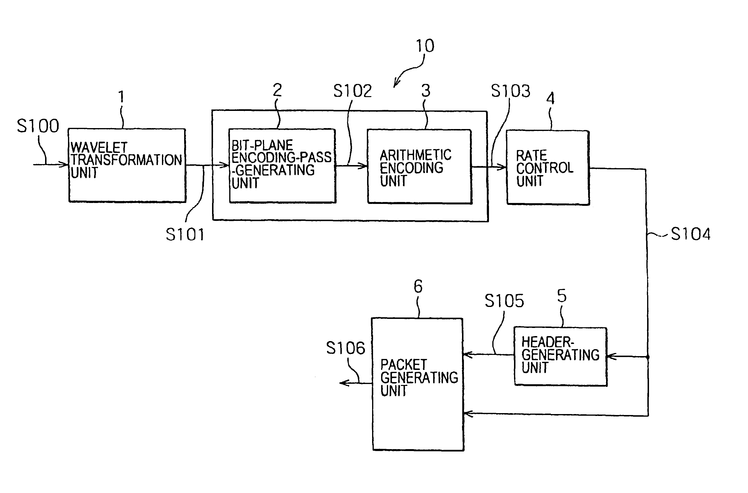
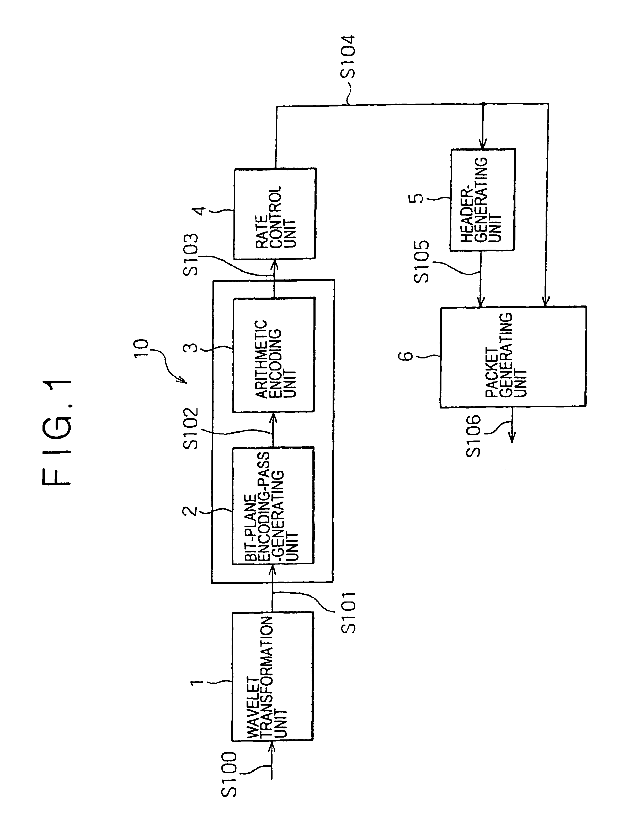
FIG. 1 is a block diagram showing the configuration of a picture-encoding apparatus implemented by an embodiment of the present invention. As shown in the figure, the picture-encoding apparatus includes:
a wavelet transformation unit 1 for carrying out wavelet transformation on an input picture to generate wavelet-transformation coefficients;
a bit-plane encoding-pass-generating unit 2 for spreading the wavelet-transformation coefficients over bit-planes ranging from an MSB (most significant bit) bit-plane to an LSB (least significant bit) bit-plane;
an arithmetic encoding unit 3 for carrying out an arithmetic encoding process in an encoding pass to generate arithmetic code;
a rate control unit 4 for controlling an encoded-data quantity so as to achieve a target encoded-data quantity for the generated arithmetic code;
a header-generating unit 5 for generating a header; and
a packet-generating unit 6 for generating a packet by addition of the header to the arithmetic code experiencing cont...
second embodiment
In the case of the first embodiment, after the processing of all the bit-plane encoding passes has been completed, the encoded-code-stream-truncating means employed in the rate control unit 4 truncates the arithmetic code stream. In order to further reduce the magnitude of the encoding load, the picture-encoding apparatus is provided with an encoding-process-stopping means. While counting the number of encoded codes included in the arithmetic code signal S103 all the time, the encoding-process-stopping means discontinues the encoding process at a point of time the target coded-data quantity is reached. In this case, it is thus necessary to count the number of encoded codes included in the arithmetic code signal S103 all the time and compare the cumulated count with the target coded-data quantity. For this reason, the operation of the rate control unit 4 is more complicated than that of the first embodiment. As described earlier, however, it is not necessary to encode the encoding pa...
third embodiment
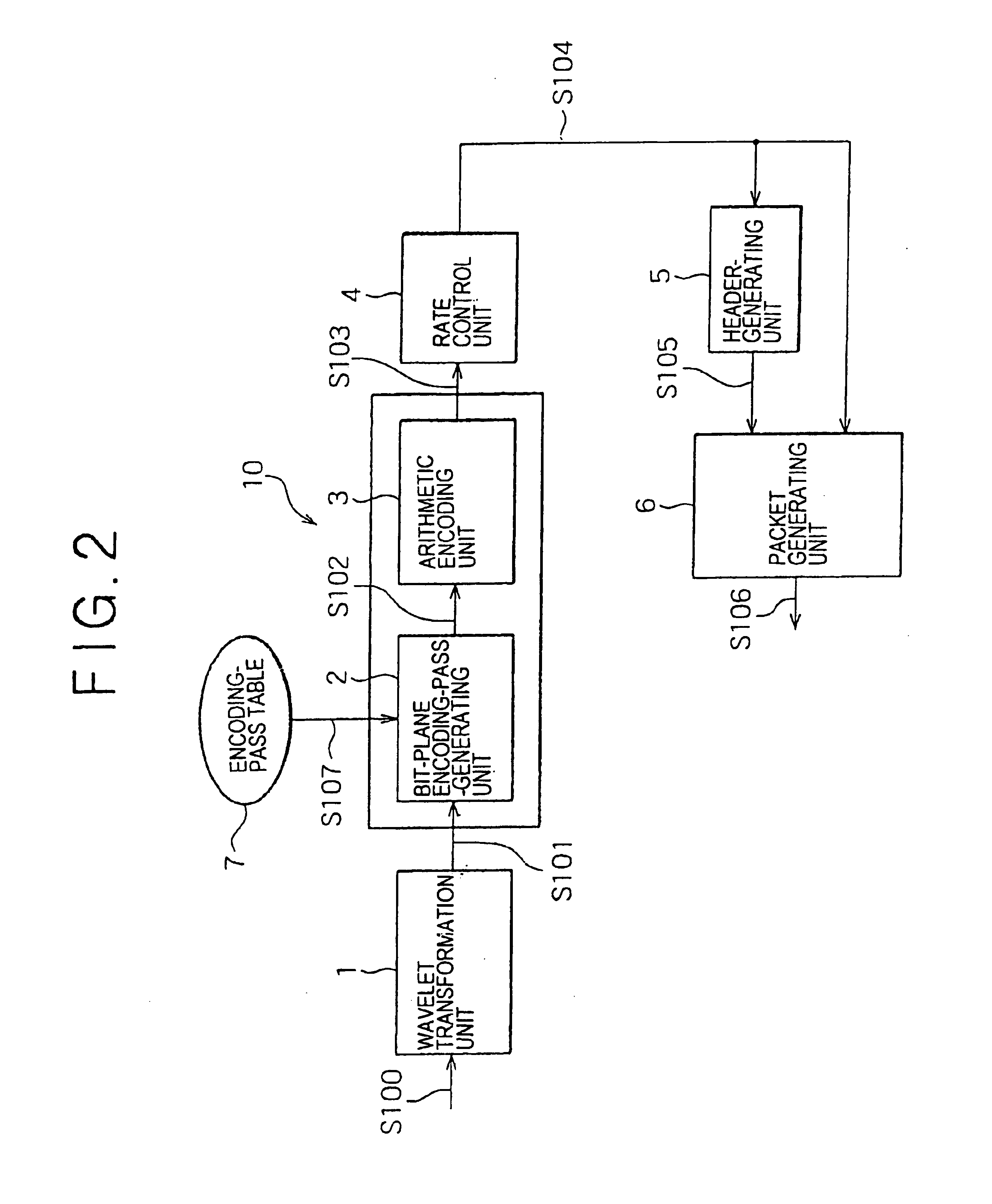
FIG. 2 is a block diagram showing the configuration of another picture-encoding apparatus implemented by a third embodiment of the present invention. In addition to the components employed in the first embodiment shown in FIG. 1, this second embodiment also includes an encoding-pass table 7 for storing the number of encoding passes for each sub-band generated as a result of the filtering.
Next, the operation of the second embodiment is explained. As is the case with the first embodiment described earlier, the wavelet-transformation coefficients S101 are spread on bit-planes, and encoding passes are generated for each of the bit-planes. The rate control is then executed to determine which encoding passes are to be selected and which encoding passes are to be truncated to achieve the target encoded-data quantity. Effects on the picture quality vary in dependence on the encoding passes and also vary in dependence on sub-bands in which the encoding passes exist.
It is thus desirable to co...
PUM
 Abstract
Description
Claims
Application Information
 - R&D
- Intellectual Property
- Life Sciences
- Materials
- Tech Scout
- Unparalleled Data Quality
- Higher Quality Content
- 60% Fewer Hallucinations
Browse by: Latest US Patents, China's latest patents, Technical Efficacy Thesaurus, Application Domain, Technology Topic, Popular Technical Reports.
© 2025 PatSnap. All rights reserved.Legal|Privacy policy|Modern Slavery Act Transparency Statement|Sitemap|About US| Contact US: help@patsnap.com


