Layout of wireless communication circuit on a printed circuit board

a wireless communication circuit and printed circuit technology, applied in the direction of printed circuit non-printed electric components association, printed circuit high frequency circuit adaptation, printed electric component incorporation, etc., can solve the problems of large power loss of bpf and insufficient low insertion loss, so as to reduce insertion power loss, reduce transmission range, and improve transmission range

Inactive Publication Date: 2005-04-05
MEDIATEK INC
View PDF1 Cites 75 Cited by
  • Summary
  • Abstract
  • Description
  • Claims
  • Application Information

AI Technical Summary

Benefits of technology

The invention provides a wireless communication circuit architecture, which can significantly reduce the insertion power loss. As a result, the transmission range is effectively improved. This is very helpful in wireless communication. The invention provides a wireless communication circuit architecture, in which the transmitting path is significantly simplified, so as to reduce the insertion loss. Also and, the fabrication cost is also reduced.

Problems solved by technology

And, the BPF has larger power loss.
In this design, the insertion loss is still not sufficient low.

Method used


Image

  • Layout of wireless communication circuit on a printed circuit board
  • Layout of wireless communication circuit on a printed circuit board
  • Layout of wireless communication circuit on a printed circuit board

Examples


Embodiment Construction

The present invention has considered the conventional issues and has introduced a novel wireless communication circuit architecture. The invention at least can reduce the insertion loss for the transmitting path. As a result, the transmission range can be effectively increased. An example is provided as an example for describing the features of the invention.

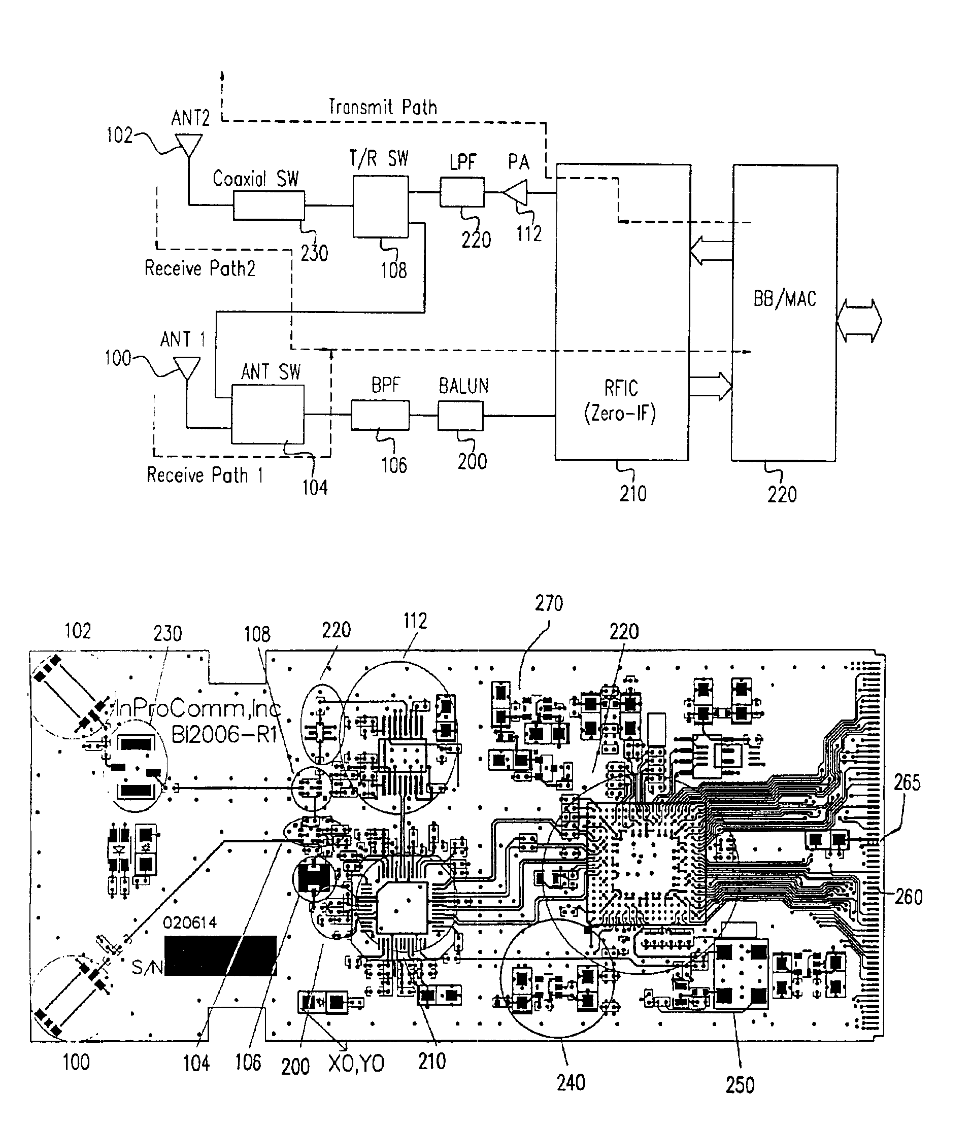
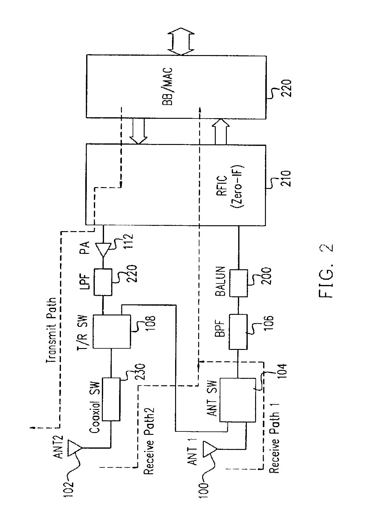
FIG. 2 is a block diagram, schematically illustrating the wireless communication circuit architecture, according to a preferred embodiment of the invention. In FIG. 2, even though the individual device elements are similar, due to the novel design of the circuit architecture, the invention has significantly produced some improved results not expected by the prior art. Two antennas 100 and 102 are used in this example for receiving RF signals and one of them is used to transmitting signals. However, the number of antennas is not limited to two. Under the same principle, based on the switching capability, the number of antennas ca...


PUM


Abstract

A layout of a wireless communication circuit on a printed circuit board (PCB), which is a rectangular board wherein a first side is a Y-axis and a second side is an X-axis. The layout has a first antenna located at a corner between the first side and the second side. An antenna switch and a first filter are located at middle y-coordinate and a X-coordinate. A RF integrated circuit (RFIC) is located after the first filter. A first regulator is located near the second side and higher than the RFIC. A media access control (MAC) is located at about a middle y-coordinate and higher than the first regulator. An oscillator is located at a corner between the second side and the third side. A second regulator is located near the fourth side and above the first regulator. A power amplifier is located near the fourth side above the RFIC. A second filter and a transmitting/receiving (T/R) switch are located before the power amplifier. A second antenna is located at a corner between the first side and the fourth side.

Description

BACKGROUND OF INVENTION1. Field of InventionThe present invention relates to wireless communication technology. More particularly, the present invention relates to a layout of a wireless communication circuit architecture on a printed circuit board (PCB), suitable for use as pPC-card for operating in the industrial, scientific and medical (ISM) band at 2.4 GHz.2. Description of Related ArtIn the last several decades, progress in radio and Very Large Scale Integrated circuit (VLSI) technology has fostered widespread use of radio communications in consumer applications. Portable devices, such as mobile radiotelephones, can now be produced having acceptable cost, size and power consumption.Although wireless technology is today focused mainly on voice communications (e.g., with respect to handheld radios), this field will likely expand in the near future provide greater information flow to and from other types of nomadic devices and fixed devices. More specifically, it is likely that fu...

Claims


Application Information

Patent Timeline
Patent Type & Authority Patents(United States)
IPC IPC(8): H04B1/38H05K1/02H05K1/18H05K1/16
CPCH04B1/38H05K1/0237H05K2201/1006H05K1/165H05K1/18H05K1/16
Inventor LIN, TSUNG-LIANGTSAI, TSUNG-LULEENG, JAN-KWO
Owner MEDIATEK INC
Why Eureka
Try Eureka