Plasma processing device and exhaust ring

a processing device and exhaust ring technology, applied in plasma techniques, energy-based chemical/physical/physicochemical processes, coatings, etc., can solve the problems of evacuating ring, abnormal discharge, bound to be damaged, etc., and achieve the effect of reducing the length of plasma leakage, preventing plasma leakage even more effectively, and ensuring a large ground area

Inactive Publication Date: 2005-04-12
TOKYO ELECTRON LTD
View PDF25 Cites 25 Cited by
  • Summary
  • Abstract
  • Description
  • Claims
  • Application Information

AI Technical Summary

Benefits of technology

According to the present invention, in which indentations are formed as well as through holes at the evacuation ring, the extent of plasma leak can be minimized and a large ground area can be assured. In addition, the plasma leak can be even more effectively prevented with the insulation coating. Since both Y2O3 and Al2O3 achieve a high degree of plasma erosion resistance, the insulation coating constituted of either of these materials improves the yield by preventing any damage from occurring readily within the processing con...

Problems solved by technology

However, the evacuation ring, which is constituted of a metal such as an aluminum alloy so as to sustain its potential at the ground potential level, is bound to be damaged by the plasma generated within the processing container.
In addition, if a sufficiently large ground area is not assured, an abnormal discharge tends to occur due to an uneven distribu...

Method used


Image

  • Plasma processing device and exhaust ring
  • Plasma processing device and exhaust ring
  • Plasma processing device and exhaust ring

Examples


Embodiment Construction

The following is a detailed explanation of the preferred embodiments of the plasma etching processing apparatus according to the present invention, given in reference to the attached drawings.

(1) Overall Structure of Etching Apparatus

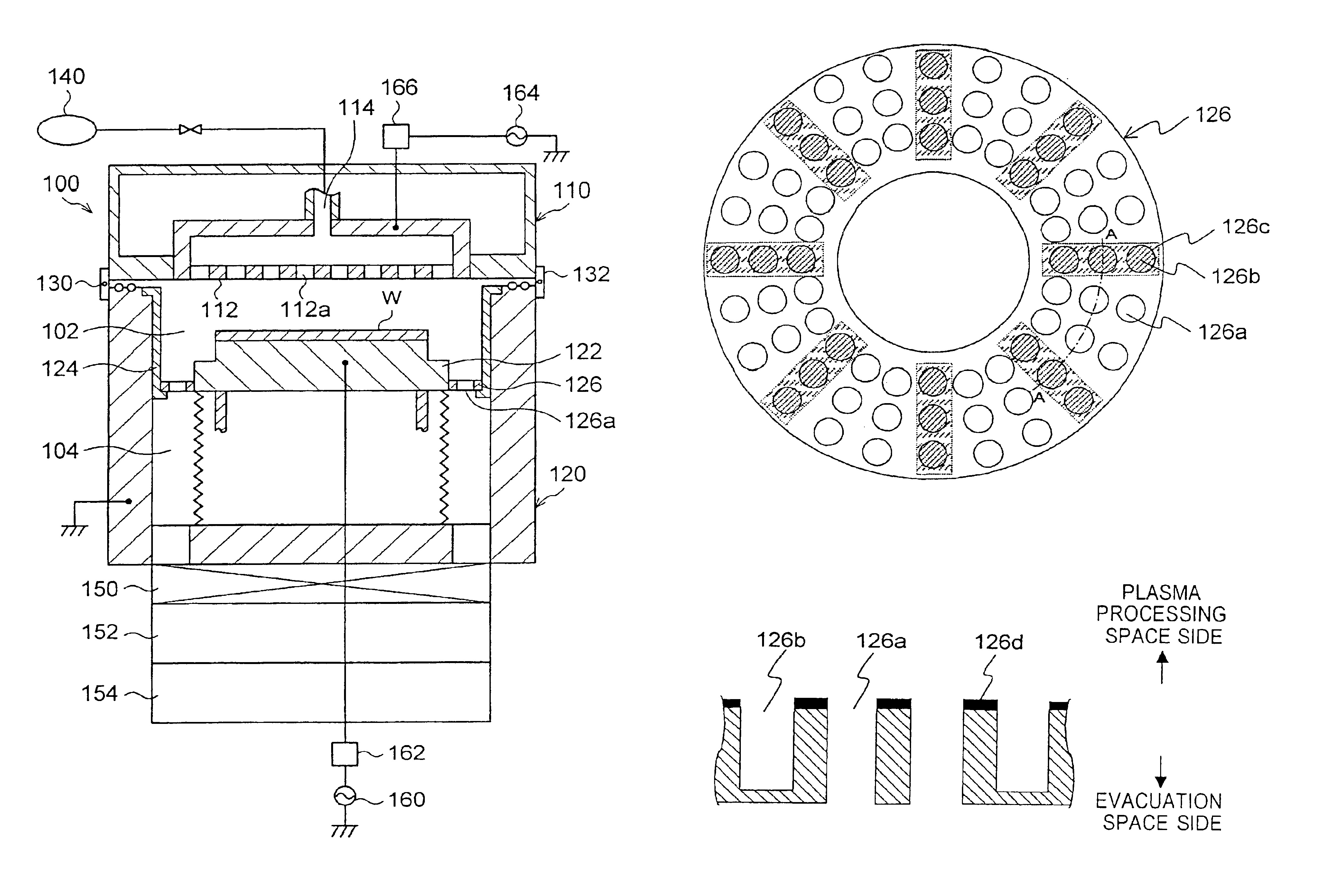
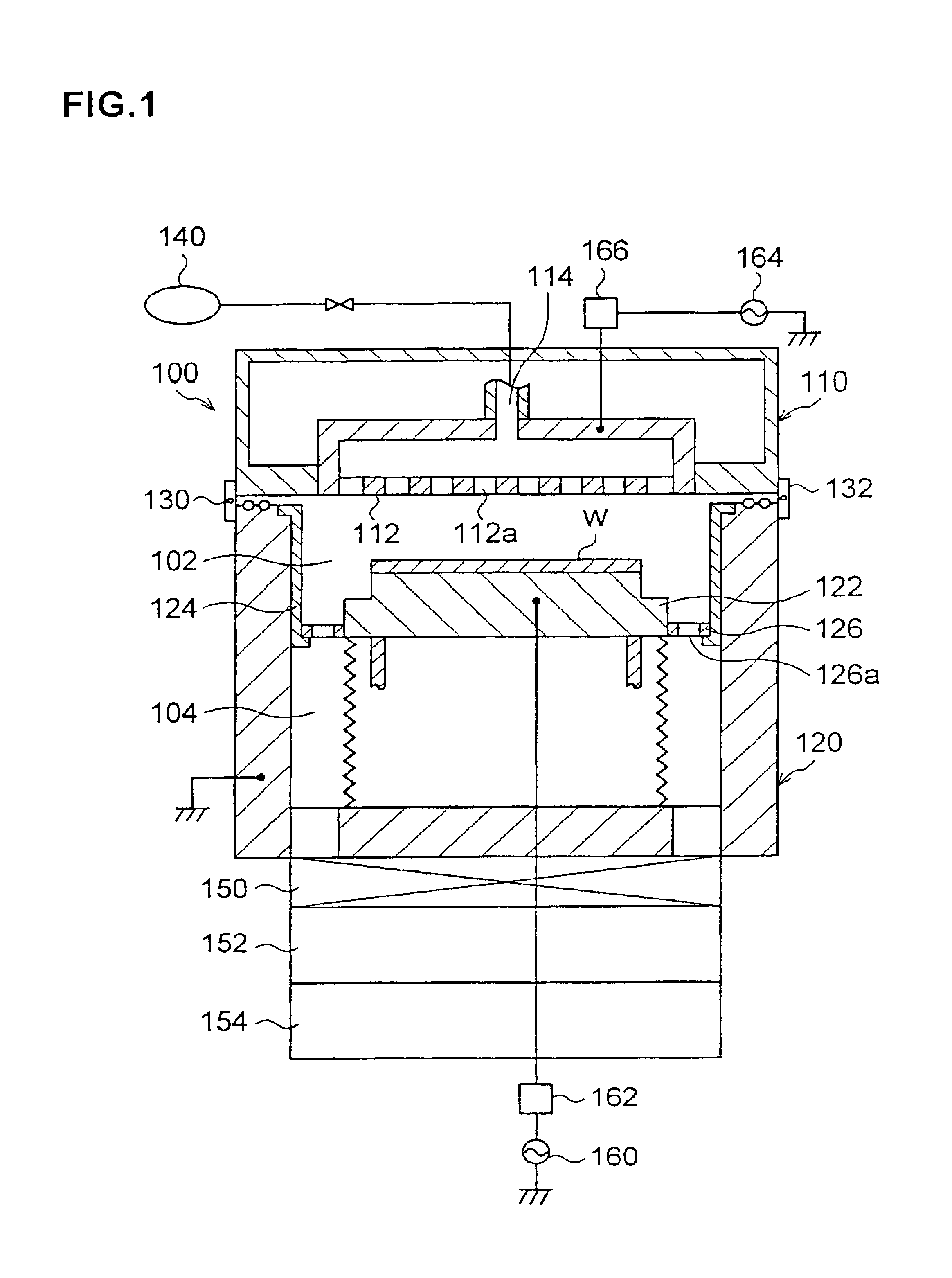
First, the structure of the etching apparatus is briefly explained. As shown in FIG. 1, a processing chamber 100 includes a ceiling unit 110 and a substantially cylindrical electrically conductive container unit 120 having an open top. The ceiling unit 110 is detachably fixed to the container unit 120 by a locking mechanism 130, and thus, the processing chamber 100 can be opened / closed freely. Inside the container unit 120, an electrically conductive lower electrode 122 on which a substrate such as a semiconductor wafer (hereafter referred to as a “wafer”) W is placed is provided. At the ceiling unit 110, an upper electrode 112 is provided to face opposite the lower electrode 122.

A plurality of gas outlet holes 112a are formed at the upper electrode 112...


PUM

PropertyMeasurementUnit
Electrical resistanceaaaaaaaaaa
Shapeaaaaaaaaaa

Abstract

A plasma processing apparatus having an evacuation ring with high plasma resistance and capable of minimizing abnormal discharge is provided. A processing chamber 100 includes a ceiling unit 110 at which an upper electrode 112 is provided and a container unit 120 having a lower electrode 122 provided to face opposite the upper electrode 112, on which a substrate can be placed. An evacuation ring 126 is provided around the lower electrode 122 so as to divide the space in the processing chamber 100 into a plasma processing space 102 and an evacuation space 104. At the evacuation ring 126, through holes 126a and blind holes 126b which are fewer than the through holes 126a and open toward the plasma processing space 102 are formed. An insulation coating constituted of Y2O3 is applied onto the surface of the evacuation ring 126 towards the plasma processing space 102.

Description

BACKGROUND OF THE INVENTIONThe present invention relates to a plasma processing apparatus.A plasma processing apparatus having an upper electrode and a lower electrode provided to face opposite each other within an airtight processing chamber is widely employed in semiconductor device manufacturing processes in the related art. Such a plasma processing apparatus adopts a structure that enables a specific type of plasma processing to be executed on a substrate with plasma generated from a process gas supplied into the processing chamber by applying high-frequency power to the upper electrode after placing the substrate on the lower electrode.In addition, an evacuation ring is mounted around the periphery of the lower electrode between the side surface of the lower electrode and the inner wall surface of a processing container, and this evacuation ring divides the space within the processing container into a processing space where the substrate is placed and an evacuation path which c...

Claims


Application Information

Patent Timeline
IPC IPC(8): H01J37/32H01L21/00B01J19/08C23C16/00C23C16/509H05H1/46H01L21/205H01L21/302H01L21/3065
CPCH01J37/3244H01J37/32834H01L21/67069H01J37/32
Inventor OGASAWARA, MASAHIROKATO, KAZUYA
Owner TOKYO ELECTRON LTD
Why Eureka
Try Eureka