
Capillary array device

a capillary array and electrophoresis technology, applied in the direction of liquid/fluent solid measurement, fluid pressure measurement, peptides, etc., can solve the problems of deterioration of electrophoresis, poor reliability, high cost of production, etc., and achieve the effect of enhancing the pressure bonding between each hollow electrode and the connection plate and minimizing the contact resistan

Inactive Publication Date: 2005-04-12
HITACHI LTD
View PDF3 Cites 19 Cited by
  • Summary
  • Abstract
  • Description
  • Claims
  • Application Information

AI Technical Summary

Benefits of technology

The present invention has an objective of cleanlily producing an inexpensive load header for a capillary array device, which introduces samples into the capillary array device and which applies a high voltage for electrophoresis. Furthermore, the present invention has an objective of producing a load header having a long-lasting reliable structure.
In one aspect of the present invention, the above-described objectives are achieved by electrically connecting a plurality of electrodes and a connection plate incorporated in a load header of a capillary array device via a spring connection instead of soldering. In order to decrease the number of operations for adhesion, a plastic holder and the electrodes are integrally molded by integration molding, thereby improving reliability. Furthermore, in order to improve reliability of the contact parts, the contact parts are covered with an adhesive or a conductive adhesive to be shielded from atmosphere, thereby preventing an oxide film having large electrical resistance from being generated on the surface of the contact parts.
Preferably, the edges of the connection plate and the outer surfaces of the hollow electrodes are electrically connected so as to enhance a pressure at the contact interfaces.
Another aspect of the invention is a capillary array electrophoresis apparatus and a capillary array in which a plurality of hollow electrodes which, together with sample inlet ends of capillaries, are immersed in samples make close contact with and are electrically connected with a conductive connection plate by the volume elasticity of the connection plate. Preferably, the hollow electrodes are secured in holes formed in the elastic connection plate. By doing so, the hollow electrodes can be secured in the connection plate by being inserted therethrough. Since the connection plate and the hollow electrodes press each other, contact resistance can be minimized.
Yet another aspect of the invention is a method for producing a load header by arranging an elastic connection plate between a holder having a plurality of hollow electrodes and a lid, and pressing the holder and the lid toward each other. By doing so, the hollow electrodes and the connection plate are electronically connected, and the holder and the lid are bonded, thereby producing a load header. Preferably, the load header is designed such that the parts of the connection plate near the hollow electrodes are pressed by the holder and the lid after the completion of the load header. As a result, pressure bonding between each hollow electrode and the connection plate can be enhanced.

Problems solved by technology

SUS pipe electrodes are used because the samples or reagents to be separated and analyzed are corrosive.
(1) Load header assembly requires a number of operations such as adhesion and bonding, which requires time and results in production at a high cost.
(2) Operations such as adhesion and bonding requires skill of the operator, and are sensitive to operation conditions and environment, which results in poor reliability.
(3) Since a strong acid soldering flux is used for soldering the connection plate and the SUS electrodes, the flux becomes ionic impurities, thereby deteriorating electrophoresis. Therefore, the narrow electrodes need to be washed both inside and outside by high-quality washing.

Method used


Image

  • Capillary array device
  • Capillary array device
  • Capillary array device

Examples


embodiment 1

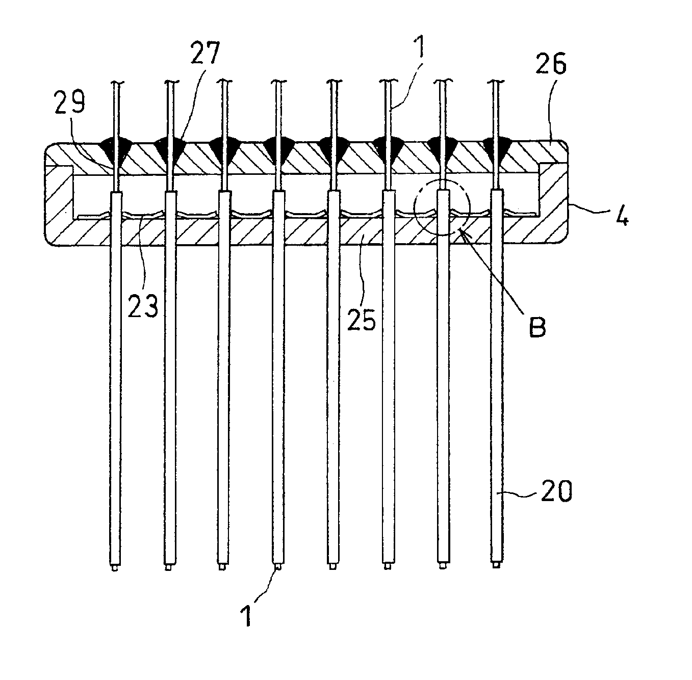
FIGS. 6A to 6C are schematic views showing one example of a load header structure where hollow electrodes and a connection plate are electrically connected by a fastening force of springs. FIG. 6A is a front cross-sectional view of the load header; FIG. 6B is a plan view of the load header without the lid; and FIG. 6C is a side cross-sectional view of the load header.

FIGS. 7A to 7C are schematic views showing a shape of the connection plate incorporated into the load header shown in FIGS. 6A to 6C. FIG. 7A is a plan view; FIG. 7B is a front view; and FIG. 7C is a side view of the connection plate, respectively.

As can be appreciated from FIGS. 6A to 6C, sixteen hollow electrodes 20 in two rows are accurately fixed to the holder 25 with an adhesive 27, and the connection plate 23 shown in FIGS. 7A to 7C is pushed in between the two rows of hollow electrodes 20. The width w of the connection plate 23 is about 10% wider than the width between the two rows of hollow electrodes 20 so that...

embodiment 2

The present embodiment relates to a load header in which hollow electrodes are inserted through a connection plate and held there by volume elasticity of the connection plate, and a method for producing the load header. The present embodiment will be described with reference to FIGS. 14 to 18.

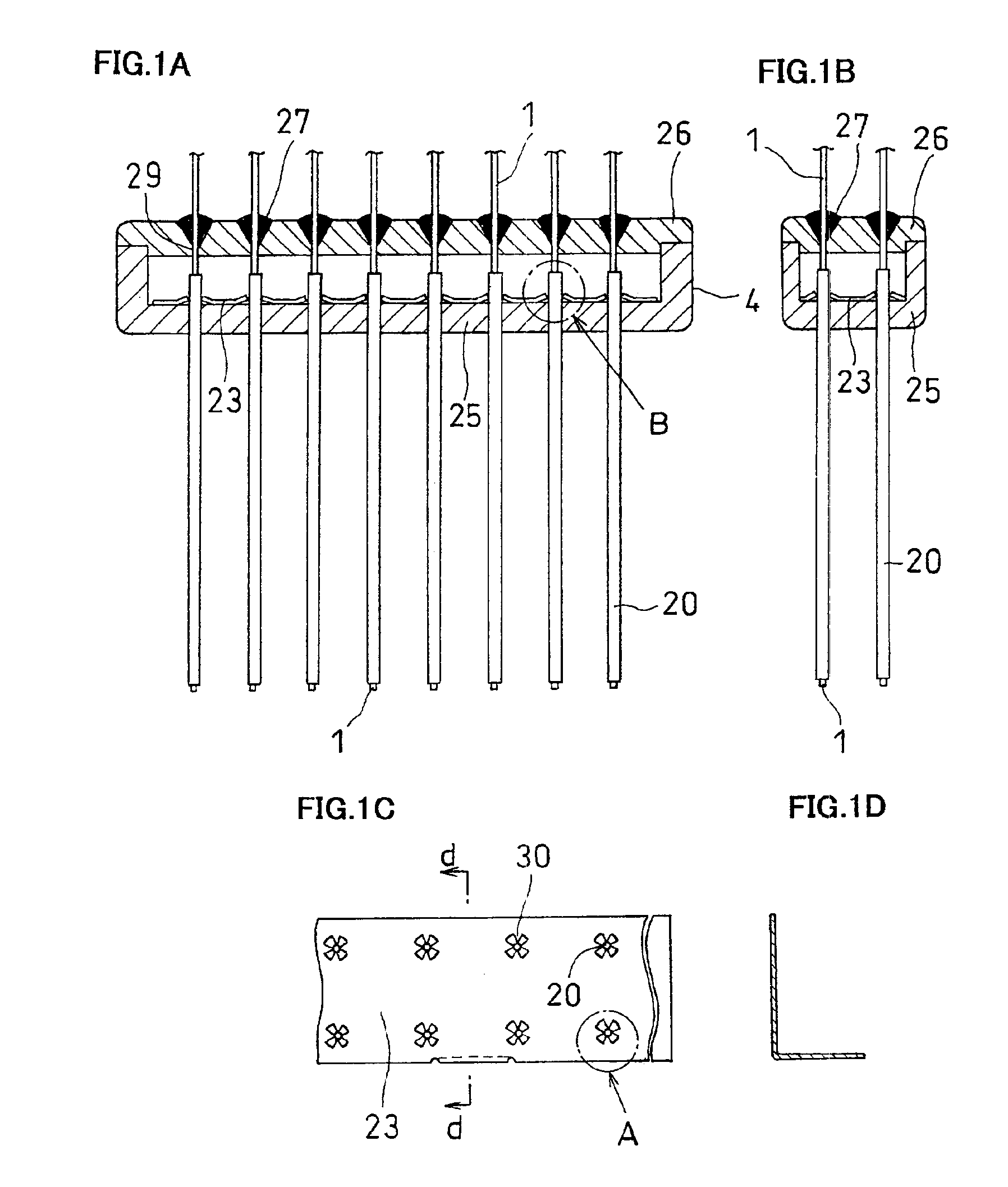
FIGS. 14A to 14D are views showing the load header according to the present embodiment. FIG. 14A is a partial front cross-sectional view of the load header; FIG. 14B is a partial side cross-sectional view of the load header; FIG. 14C is a schematic view of the connection plate and FIG. 14D is a detailed view of part A in FIG. 14A.

The load header is provided with: ninety-six hollow electrodes 20; a connection plate 23 bonded with the ninety-six hollow electrodes and connected to a high-voltage contact of an electrophoresis apparatus to apply a high voltage to the hollow electrodes; a plastic holder 25 for accommodating the connection plate with the hollow electrodes 20 arranged in a matrix of 8×...

embodiment 3

The present embodiment relates to a method for producing the load header in which the hollow electrodes are inserted into the insertion holes of the connection plate and the lid is secured to the holder by ultrasonic bonding at the same time. Hereinafter, the present embodiment will be described with reference to FIGS. 19A to 19D. FIG. 19A is a cross-sectional view showing a state prior to ultrasonic bonding; FIG. 19B is a cross-sectional view showing a state after the bonding; FIG. 19C is a flowchart of production; and FIG. 19D is a cross-sectional view showing a part near the hollow electrode after the bonding in detail.

In the same manner as Embodiment 2, ninety-six hollow electrodes 20 are secured to the holder 25. Then, as shown in FIG. 19A, the connection plate 23 and the lid 26 are placed in this order on the holder 25 where the ninety-six (12×8) hollow electrodes are accurately arranged and fixed with the adhesive. The insertion holes 130 of the connection plate 23 and the gu...


PUM

PropertyMeasurementUnit
pressureaaaaaaaaaa
inner diameteraaaaaaaaaa

Abstract

The present invention easies a connection between electrodes of a capillary array device and a connection plate for supplying a high voltage to the electrodes.According to the present invention, a connection plate 23 and hollow electrodes 20 are connected without solder but via a spring force. Alternatively, the hollow electrodes 20 can be connected to the connection plate 23 by utilizing volume elasticity of the connection plate.

Description

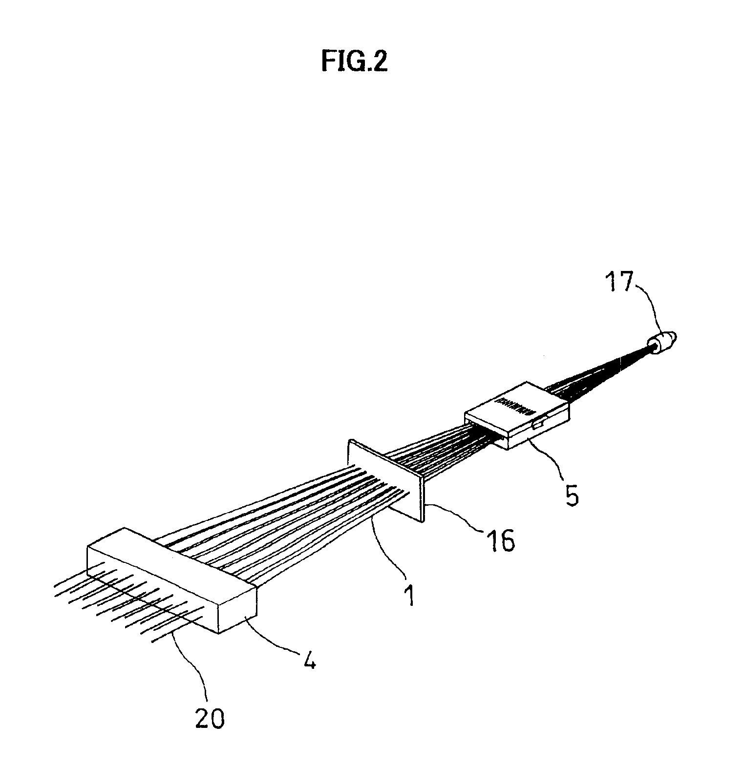
FIELD OF THE INVENTIONThe present invention relates to a capillary array electrophoresis apparatus for separating and analyzing a sample such as DNA and a protein, to a capillary array incorporated in the electrophoresis apparatus, and to a method for producing the capillary array.BACKGROUND OF THE INVENTIONA technique is well known in which a capillary device incorporating a combination of a plurality of capillaries is used for supplying and running an electrophoresis medium together with a sample to be analyzed or separated to utilize a target sample for separation and analysis. In addition, a technique where a sample such as fluorescence-labeled DNA or protein is supplied to a capillary is described, for example, in U.S. Pat. Nos. 5,366,608, 5,529,679, 5,516,409, 5,730,850, 5,790,727, 5,582,705, 5,439,578 and 5,274,240. In view of the throughput for separation and analysis, use of multi-capillaries is more advantageous than an electrophoresis method employing a flat gel. Japanese...

Claims


Application Information

Patent Timeline
Patent Type & Authority Patents(United States)
IPC IPC(8): G01N27/447
CPCG01N27/44704G01N27/44782G01N27/44743
Inventor KASAI, SYOUZOUOKISHIMA, YOSHIYUKIMORIOKA, TOMONARISHIMIZU, YASUSHITANAKA, HIROYUKIFURUKAWA, TAKAYASUSHIMODA, NORIYUKIUGAI, SEIICHI
Owner HITACHI LTD
Learn More