Transformerless, load adaptive speed controller

a transformerless, load-adaptive technology, applied in the direction of motor/generator/converter stopper, dynamo-electric converter control, ac network to reduce harmonics/ripples, etc., can solve the problem of reducing part-load fuel efficiency, limiting the maximum output or overload power of the engine, and ic, so as to achieve more efficient generation of power and reduce emissions.

Inactive Publication Date: 2005-04-12
YOUTILITY
View PDF24 Cites 130 Cited by
  • Summary
  • Abstract
  • Description
  • Claims
  • Application Information

AI Technical Summary

Benefits of technology

While adaptable in many forms, the invention is a variable speed generator, load adaptive engine speed control, generator field control/voltage regulator and power conditioning inverter suitable for use in modern power distribution systems. In addition to all

Problems solved by technology

A problem with the state of the art systems is that typical internal combustion (IC) engine generator systems must rotate at a fixed speed to provide a fixed frequency output.
This dramatically limits the engines maximum output or overload power, decreases part-load fuel efficiency, and consequently increases emissions/K Whr of power produced.
Another problem with the existing systems is that the distribution system is subject to non-linear, high harmonic content and unbalanced loading.
In distributed power applications, high harmonic content or unbalanced loads may lead to utility grid instability, resonances or other unanticipated distribution system behavior that may cause catastrophic failure of the distribution system components.
Such a failure can result in damage to equipment and possibly personal injury.
Whether grid connected or grid independent, typical generators demonstrate poor output waveform total harmonic distortion (THD) when connected to any non-linear loads.
This causes the generator output voltage waveform to rapidly degrade while simultaneously increasing generator losses and operating temperatures, and decreasing the power actually coupled from the e

Method used


Image

  • Transformerless, load adaptive speed controller
  • Transformerless, load adaptive speed controller
  • Transformerless, load adaptive speed controller

Examples


Embodiment Construction

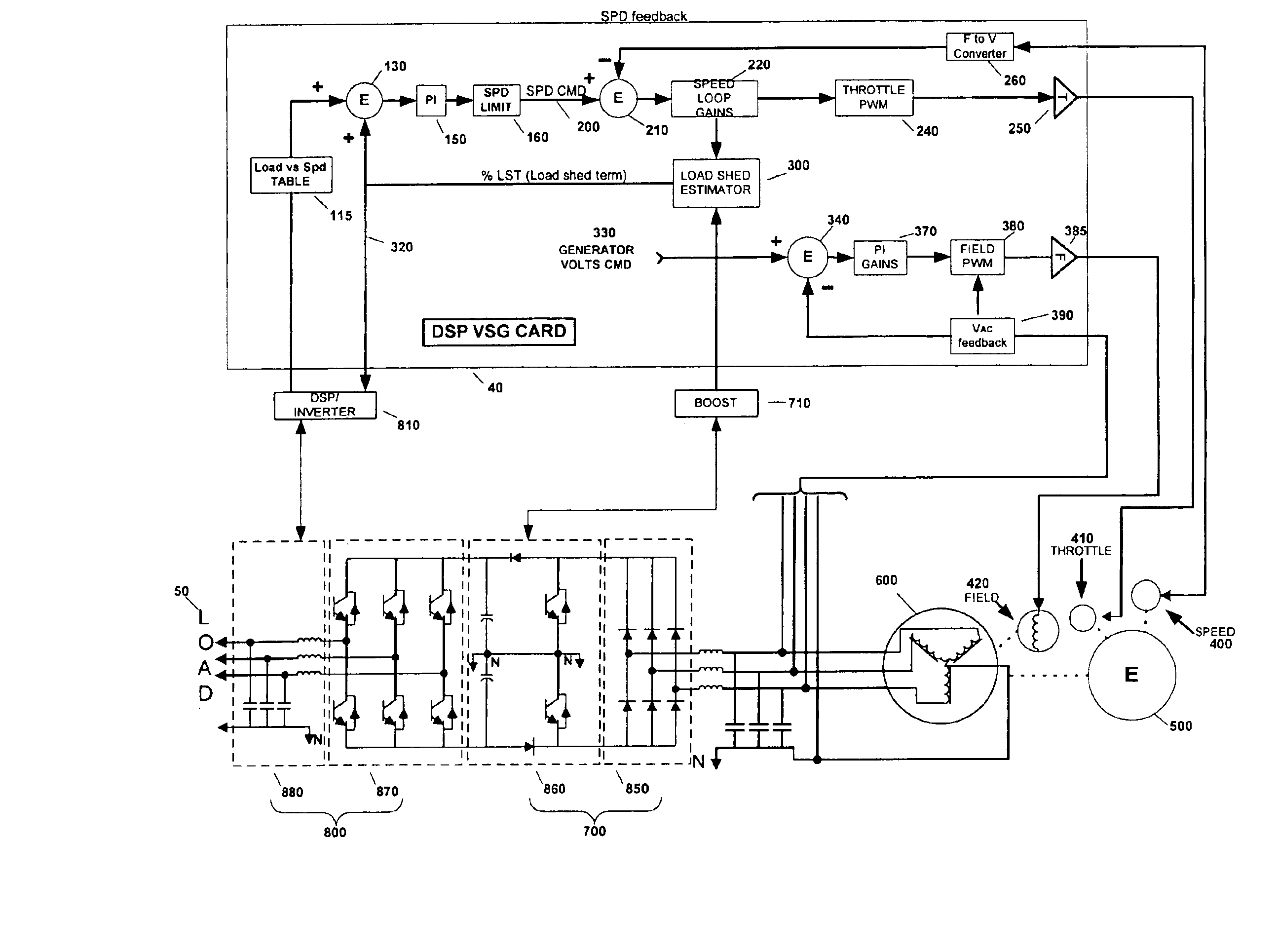
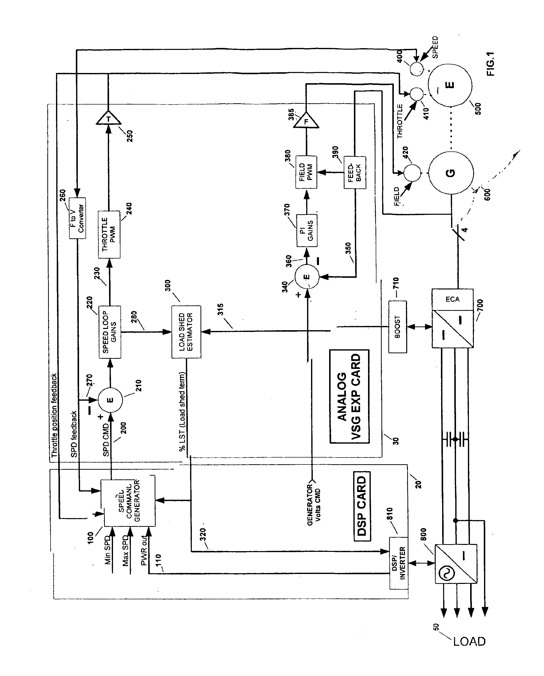
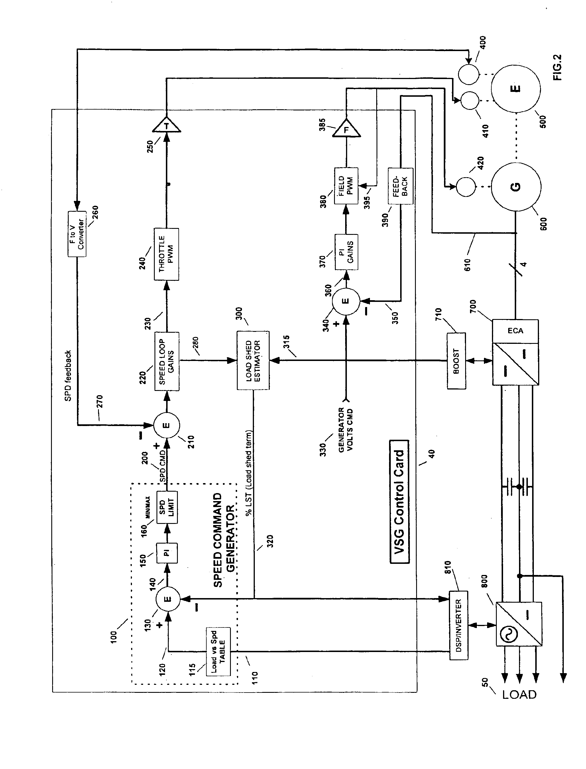
Referring to FIG. 1, one embodiment of the present invention is depicted in block diagrammatic form. The variable speed generator system according to this embodiment couples the generator 600 and engine 500 through a power conditioning system (PCS) 20, 30 having a speed versus load controller wherein the speed command generator resides in the digital signal processing (DSP) circuit card 20. The speed and field control loops reside on the analog expansion card 30. The output from the generator 600 and engine 500 are coupled through an enhanced conduction angle (ECA) dual boost DC bus voltage regulator 700 and dual boost control section 710. And, there is an inverter 800 that is tied to the load.

There are many benefits of connecting a generator to a load through a power conditioning system (PCS). The generator is isolated from load-induced harmonics and imbalances, such as unequal or non-sinusoidal loads on each phase, and the output voltage regulation is improved. The output impedanc...


PUM


Abstract

The invention in the simplest form is an improved variable speed engine/generator set with an integrated power conditioning system and control method, used to generate high quality AC power with optimum fuel efficiency and reduced emissions. The variable speed generator control scheme allows for load adaptive speed control of engine and generator field. The transformerless power inverter topology and control method provides the necessary output frequency, voltage and/or current waveform regulation, harmonic distortion rejection, and provides for single phase, or unbalanced loading.

Description

FIELD OF THE INVENTIONThe present invention relates to power generators, power converters and distribution schemes for power distribution. More specifically, the present invention relates to a variable speed engine / generator set with an integrated power conditioning system and control method to generate high quality AC power with optimum efficiency and reduced emissions.BACKGROUND OF THE INVENTIONElectric power distribution is a necessary component of systems that operate with electronic power or in the distribution of electronic power. For example, most electronic equipment is a load that is connected to a utility grid, wherein power arrives in one form and is transferred and transformed into a form more suitable for the equipment.The distribution of electric power from utility companies to households and businesses utilizes a network of utility lines connected to each residence and business. The network or grid is interconnected with various generating stations and substations tha...

Claims


Application Information

Patent Timeline
IPC IPC(8): H02J3/30H02J9/06H02J3/28H02M5/458H02M5/00H02J3/18H02J3/01H02P9/48
CPCH02J3/30H02J9/062H02P9/48H02M5/458H02J3/01H02J3/1864Y02E40/40Y02E60/16H02P2101/45H02J3/00125
Inventor WELCHES, RICHARD SHAUNHOHM, DANIEL P.WEN, JIANLEROW, KEVIN EGRIESSEL, RICHARDO'REILLY, THOMAS
Owner YOUTILITY
Why Eureka
Try Eureka