Adaptive ballast control IC

a ballast control and adaptive technology, applied in the direction of electric variable regulation, process and machine control, instruments, etc., can solve the problems of poor quality, poor performance, field failure, etc., and achieve the effect of improving performance, improving immunity against system tolerances and variations, and being competitive on cos

Inactive Publication Date: 2005-04-12
INFINEON TECH AMERICAS CORP
View PDF4 Cites 22 Cited by
  • Summary
  • Abstract
  • Description
  • Claims
  • Application Information

AI Technical Summary

Benefits of technology

[0035]The disclosed 8-pin adaptive ZVS and MCS ballast control IC is especially well adapted for CFL applications. Novel control and sensing techniques have been developed to realize important ballast functions without compromising IC pin count. The resulting system solution has better performance than the comparative self-oscillating solution, uses fewer components and is competitive on cost. This IC solution offers higher immunity against system tolerances and variations and can be scaled up or down easily for lower or higher power levels. Finally, the simplicity of this new IC meets the needs of the marketplace.

Problems solved by technology

This approach is very simple in nature but has the following disadvantages:Non self-starting (requires a diac and additional circuitry);Requires additional free-wheeling diodes;Operating frequency determined by bipolar transistor storage time and toroid saturation;Unreliable, “always hot” positive-temperature-coefficient (PTC) thermistor used for preheat;No smooth frequency ramping during ignition;No protection against lamp non-strike or open filament conditions;Capacitive-mode operation; andBase drive limitations at higher powers.
These disadvantages can lead to component and load tolerances and / or catastrophic failure of ballast output stage components, which can result in poor performance, poor quality, and / or field failures.

Method used


Image

  • Adaptive ballast control IC
  • Adaptive ballast control IC
  • Adaptive ballast control IC

Examples


Embodiment Construction

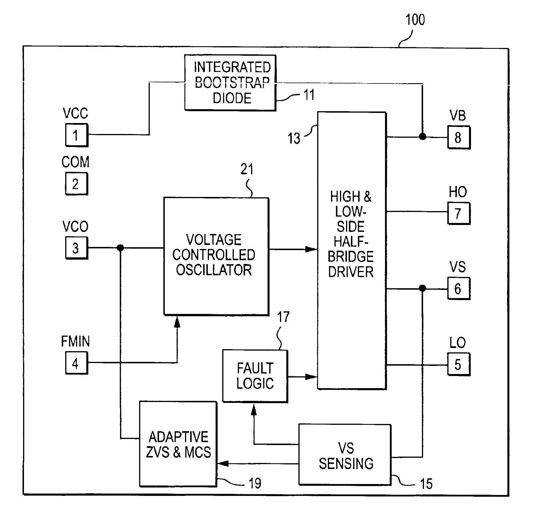
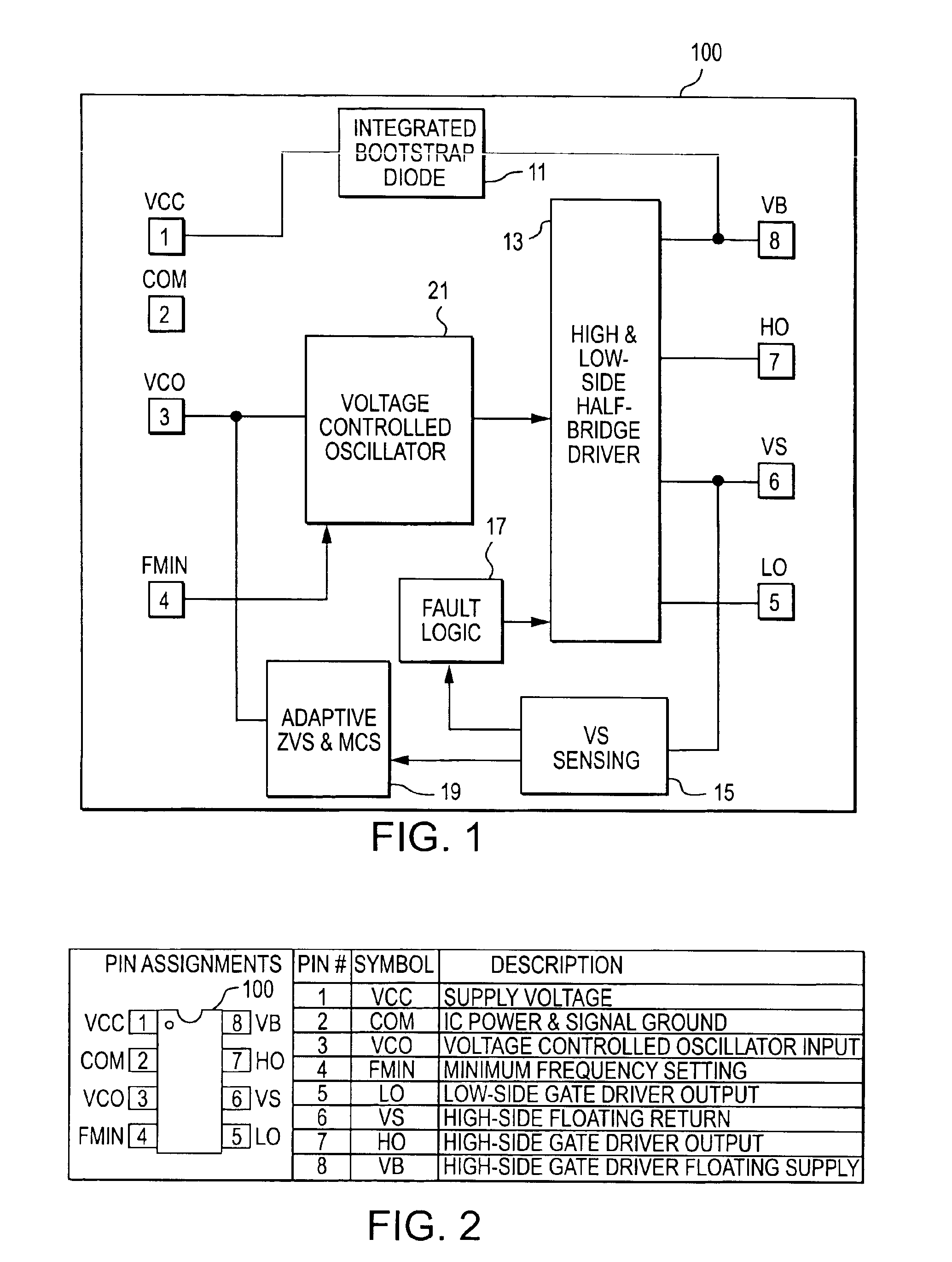
[0047]A simple, low-cost IC solution has been developed that integrates multiple CFL functions, plus the high- and low-side half-bridge driver (FIG. 1). In order to minimize packaging costs, the IC has been limited to 8 pins so that it fits into a standard SO8 or DIP8 package. The half-bridge driver requires four pins 8, 7, 6 and 5 (VB, HO, VS and LO), the power supply and return require two pins 1 and 2 (VCC and COM), and one pin 4 is used to program the minimum frequency (FMIN).

[0048]This results in only one control pin 3 available for the ballast functions. To achieve this, a voltage-controlled oscillator analog input pin (VCO) is used together with an internal adaptive control system and method, and a half-bridge voltage sensing technique to realize all of the preheat, ignition, running and fault protection functions.

[0049]FIG. 1 shows a block diagram of the IC, and FIG. 2 is a table of pin assignments of the IC. Referring to FIGS. 1 and 2, the IC 100 has an integrated bootstrap...


PUM


Abstract

An integrated circuit for controlling a power supply circuit which delivers power to a load circuit that includes a fluorescent lamp, comprising ballast control and drive circuitry that provides drive signals to the power supply circuit, receives sense signals indicating operating conditions of at least one of the power supply circuit and the load circuit, and responds to the sense signals by modifying the drive signals; and including adaptive zero-voltage-switching and minimum-current-switching (ZVMCS) circuitry, wherein the ZVMCS circuitry senses an output of the power supply circuit, and in response thereto, controls the drive circuitry to maintain the power supply circuit under ZVMCS conditions. The power supply circuit includes a half-bridge circuit with low and high side power devices, the drive signals including low side drive signals to control the low side power device and high side drive signals to control the high side power device; the ballast control and drive circuitry including a low side drive output for providing the low side drive signals to the low side power device and a high side drive output for providing the high side drive signals to the high side power device. The ZVMCS circuit senses an output voltage and / or current at the half-bridge circuit between said high side and low side power devices at a switching time of one of the power devices, and controls the drive signals so as to maintain the output voltage and / or current near or at zero at said switching time.

Description

CROSS-REFERENCE TO RELATED APPLICATIONS[0002]The present application is based upon and claims priority of U.S. Provisional Applications Nos. 60 / 395,093 and 60 / 395,473 filed respectively on Jul. 9 and 10, 2002 the disclosures of which are incorporated by reference herein.[0003]It is related to U.S. Provisional Application No. 60 / 482,334 filed on Jun. 24, 2003, also incorporated by reference.BACKGROUND OF THE INVENTION[0004]Many linear electronic ballasts for fluorescent lighting applications that are sold on the market today include a standard ballast control IC, ASIC or micro-controller. These control ICs perform a variety of functions ranging from power factor correction to lamp / ballast control and have helped meet the technical requirements of new lamp types while reducing component count and cost. In self-ballasted compact fluorescent lamps (CFLs), the self-oscillating bipolar transistor solution is popular due to lower cost, lower component count and smaller size than the equiva...

Claims


Application Information

Patent Timeline
Patent Type & Authority Patents(United States)
IPC IPC(8): H05B41/282H05B41/285H05B41/28H05B41/24
CPCH05B41/2828H05B41/2856H05B41/2853Y02B20/186Y02B20/00
Inventor RIBARICH, THOMAS J.
Owner INFINEON TECH AMERICAS CORP
Why Eureka
Try Eureka