Exhaust gas purifying system for internal combustion engines

a technology for exhaust gas purification and internal combustion engines, which is applied in the direction of machines/engines, electrical control, instruments, etc., to achieve the effect of relatively inexpensive detection of a specific gas

Inactive Publication Date: 2005-04-19
DENSO CORP
View PDF7 Cites 11 Cited by
  • Summary
  • Abstract
  • Description
  • Claims
  • Application Information

AI Technical Summary

Benefits of technology

[0005]Therefore, the invention contemplates to provide an exhaust gas purifying system for an internal combustion engine, which is enabled to detect a specific gas relatively inexpensively by intentionally changing a detection sensitivity (or reaction) of an air / fuel ratio sensor to the specific gas.
[0006]In order to achieve this object, a system of the invention gives an air / fuel ratio detecting sensor made by arranging an electrode at a solid electrolyte element, for detecting the air / fuel ratio in the exhaust gas from the engine, priority in sensitivity to a specific gas in the exhaust gas. In order to change this detection sensitivity to the specific exhaust gas, the temperature of the solid electrolyte element is adjusted. As a result, it is possible to improve the detection characteristic of an exhaust gas component to be reduced or detected.
[0007]The system of the invention, moreover, adjusts the temperature of the solid electrolyte element in accordance with the running state of the engine so as to change the detection sensitivity of an air / fuel ratio detecting sensor made by arranging an electrode at the solid electrolyte element, for detecting the air / fuel ratio in the exhaust gas from the engine, to the specific exhaust gas. As a result, it is possible to improve the detection characteristic to the exhaust gas component to be reduced or detected.

Problems solved by technology

These technologies can improve the detection precision to the air / fuel ratio but not the detection precision (or reaction) to a specific gas.

Method used


Image

  • Exhaust gas purifying system for internal combustion engines
  • Exhaust gas purifying system for internal combustion engines
  • Exhaust gas purifying system for internal combustion engines

Examples


first embodiment

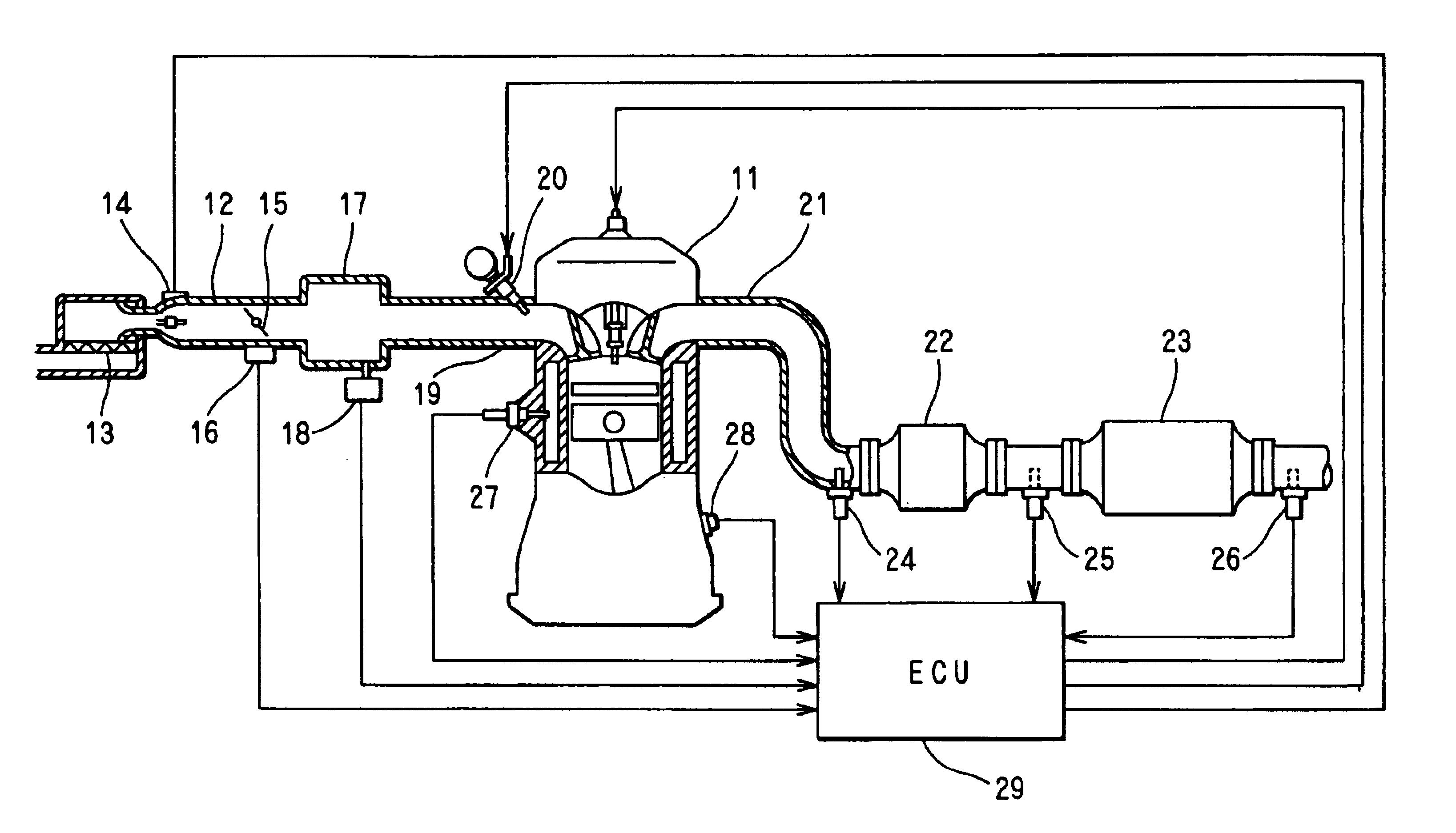
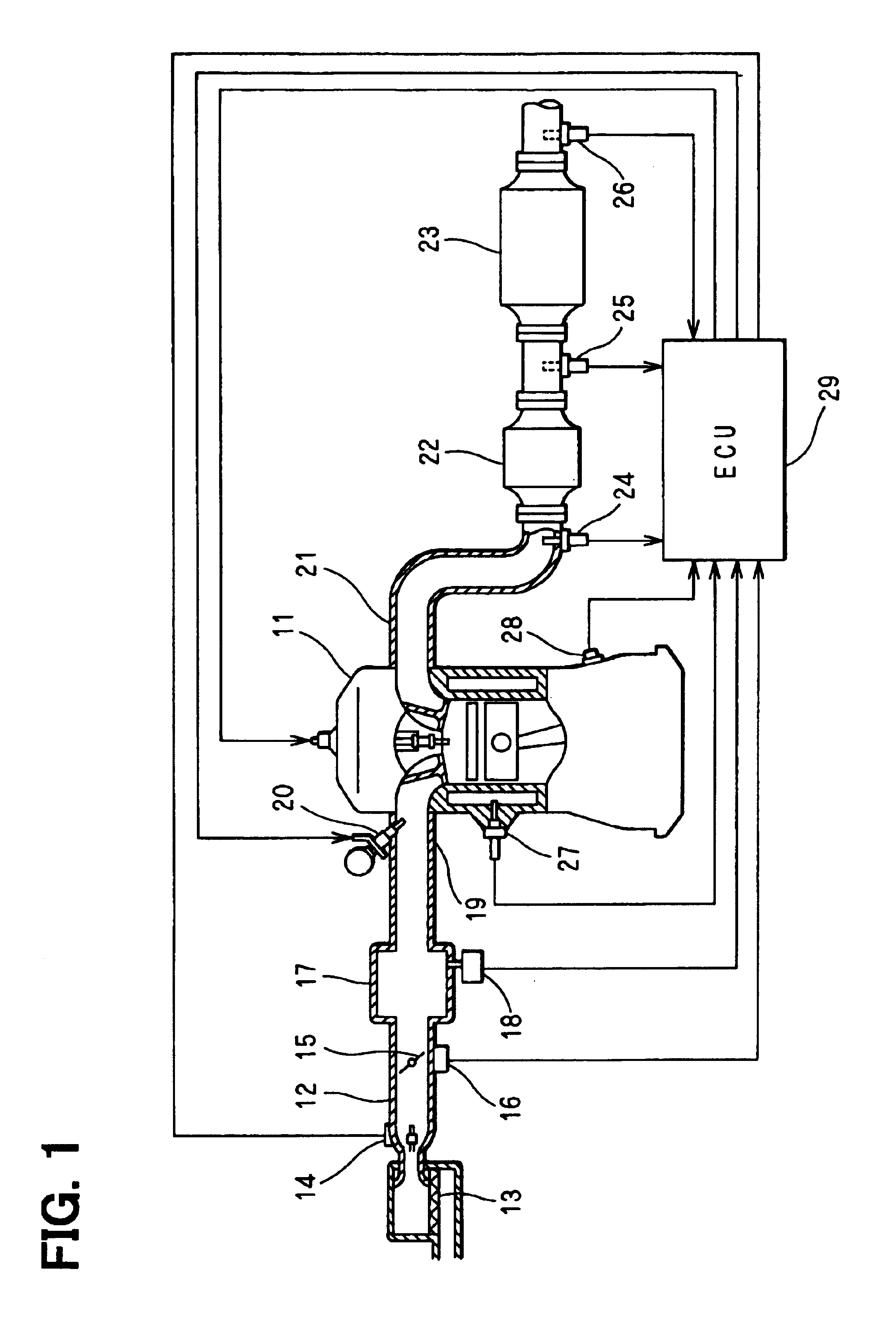
[0028]First of all, the schematic construction of an engine control system will be described with reference to FIG. 1. An internal combustion engine 11 is provided, at the most upstream portion of its intake pipe 12, with an air cleaner 13 and, on the downstream side of the air cleaner 13, with an air flow meter 14 for detecting the amount of intake air. On the downstream side of this air flow meter 14, there are disposed a throttle valve 15 and a throttle opening sensor 16 for detecting the degree of throttle opening.

[0029]On the downstream side of the throttle valve 15, moreover, there is disposed a surge tank 17, which is provided with an intake pipe pressure sensor 18 for detecting an intake pipe pressure. On the other hand, the surge tank 17 is provided with an intake manifold 19 for introducing air into the individual cylinders of the engine 11. In the vicinity of the intake port of each cylinder in the intake manifold 19, there is attached a fuel injection valve 20 for inject...

second embodiment

[0105]In the second embodiment, the target impedance setting routine is differentiated from that in the first embodiment (FIG. 14), as shown in FIG. 18. The flow chart of FIG. 18 is started at a predetermined timing. When this routine is started, it is determined at step 501 whether or not the fuel supply is resumed from the fuel cut-off (F / C). At step 502, moreover, it is determined whether or not the fuel supply is being increased due to the return from the fuel cut-off. In case the answer of either of the determinations is No, the routine advances to step 506, at which the target impedance R is set to 100 Ω (e.g., 570° C.) for the normal temperature control.

[0106]In case the return from fuel cut-off is determined at step 501 and in case it is determined at step 502 that the fuel is being increased, the routine advances to step 503, at which it is determined whether or not the first oxygen sensor output VOX is less than 0.45 V (stoichiometry). In case of more than 0.45 V, it is de...


PUM


Abstract

A first oxygen sensor is mounted on an exhaust pipe. An ECU determines an electric power to be fed to a sensor heater, by a heater control quantity calculating block, in accordance with a difference between an actual impedance and a target impedance calculated by a running condition determining block and a specific gas sensitivity priority determining block. As a result, the detection sensitivity of the oxygen sensor to a rich component or a lean component is improved according to the running condition. This improved output is detected by an output detecting block and reflected on the air / fuel ratio control so that an air / fuel ratio is controlled thereby.

Description

CROSS REFERENCE TO RELATED APPLICATION[0001]This application is based on and incorporates herein by reference Japanese Patent Application No. 2002-121306 filed on Apr. 23, 2002.FIELD OF THE INVENTION[0002]The present invention relates to an exhaust gas purifying system for an internal combustion engine, which is provided with a heater control device for controlling a heater attached to a sensor for detecting the air / fuel ratio in the exhaust gas of the internal combustion engine.BACKGROUND OF THE INVENTION[0003]In an exhaust gas purifying system, which is provided with an air / fuel ratio sensor upstream of a catalyst disposed on the exhaust pipe of the internal combustion engine so that the output of the air / fuel ratio sensor may approach a target air / fuel ratio. Moreover, another air / fuel ratio sensor is further disposed downstream of the catalyst so that the target air / fuel ratio upstream of the catalyst may be corrected on the basis of the output of that downstream air / fuel ratio ...

Claims


Application Information

Patent Timeline
Patent Type & Authority Patents(United States)
IPC IPC(8): F01N3/10F02D41/14F01N7/00F01N7/02F02D45/00F01N13/02
CPCF01N3/10F01N13/009F02D41/1456F02D41/1494F02D41/1496F01N13/0093F02D41/1441F01N2570/00F01N2570/12F01N2570/14
Inventor IIDA, HISASHIHARA, MITSUOSUZUKI, HIDEKIOKAMOTO, YOSHIYUKI
Owner DENSO CORP
Why Eureka
Try Eureka