Adaptive optic with discrete actuators for continuous deformation of a deformable mirror system

a mirror system and actuator technology, applied in the field of high-precision lithography exposure systems, can solve the problems of reducing size, reducing the efficiency of lithography exposure, and reducing the size of reticles for electron beam projection, so as to achieve the effect of optimizing optical performan

Inactive Publication Date: 2005-04-19
NIKON CORP
View PDF32 Cites 32 Cited by
  • Summary
  • Abstract
  • Description
  • Claims
  • Application Information

AI Technical Summary

Benefits of technology

[0012]It is therefore an object of the present invention to provide an optical system operable at EUV wavelengths and controlling one or more adaptive optical elements for optimization of optical performance and minimization of aberrations to less than an allowable deformation limit with reference to an optimal design shape of the adaptive optical elements.
[0013]The invention provides an apparatus for controlling optical element deformation continuously over the surface of a deformable optical element, where the reactive forces used to deform the mirror are applied at a plurality of discrete points to achieve a continuous deformation adequate to correct aberrations in an optical system operating at EUV wavelengths. Aberrations are detected with reference to a design shape In one embodiment pressure is applied directly to contiguous local areas of the optical element via a plurality of air bellows arrayed conformably to the back surface of a deformable optical element. In another embodiment a thermal gradient to an optical element having a thermal coefficient of expansion is established via a plurality of thermal actuators arrayed conformably to the back surface of a deformable optical element. By controlling each of the plurality of actuators in combination there is provided a desired or aberration-compensating performance of the optical element.

Problems solved by technology

Nevertheless, resolution of extremely small features requires correspondingly short wavelengths of radiation.
Accordingly, use of X-rays for lithographic exposure are known but not widely known due to the requirement for fabrication of an exposure mask at the same minimum feature size as the final desired pattern since reduction of the size of the pattern cannot be achieved with X-rays.
However, between these two techniques, reticles for electron beam projection are generally far more expensive than optical reticles and, perhaps more importantly, require many more exposures to form a complete integrated circuit pattern since the exposure field at the chip is comparatively more limited in electron beam projection systems.
Such fully reflective systems are usually more complex than lens systems since interference between illumination of the reticle and illumination of the target with the projected pattern must be avoided.
While techniques of measurement of wave-front aberrations are well-known and sufficient to accurately characterize the performance of optical systems and elements thereof, practical arrangements for conducting such measurements are difficult and complex.
Measurements performed between exposures cannot be regarded as measurements of optical performance during the exposure itself and do not directly characterize the lithographic image itself, but are often the only practical solution at the current state of the art even though sources of error may be introduced thereby.
Active optics are known but have not been widely used to date in such systems.
However, mechanical actuators which deflect portions of the optical element (such as are disclosed therein) may present numerous problems of stability, hysteresis and the like and may be unsuitable for optical element deformations which may be only a relatively small fraction of a very short wavelength.

Method used


Image

  • Adaptive optic with discrete actuators for continuous deformation of a deformable mirror system
  • Adaptive optic with discrete actuators for continuous deformation of a deformable mirror system
  • Adaptive optic with discrete actuators for continuous deformation of a deformable mirror system

Examples


Embodiment Construction

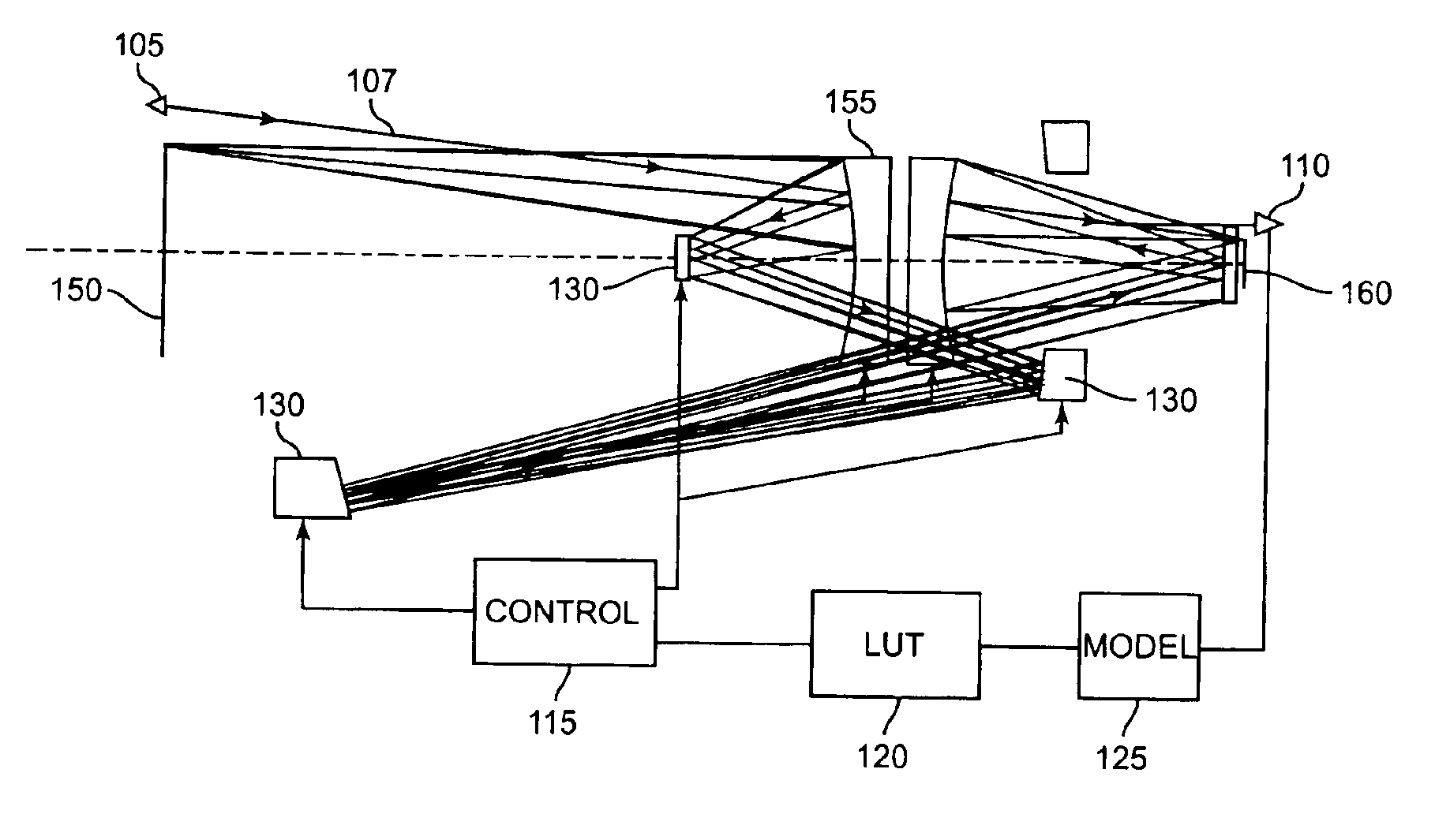
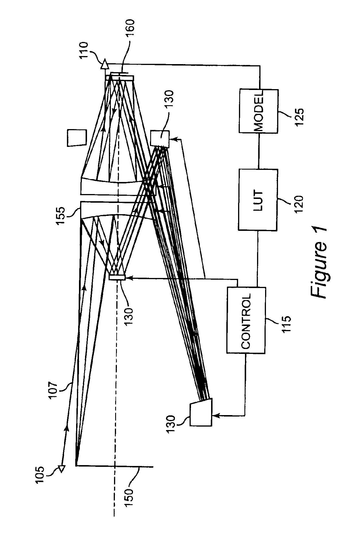
[0020]Referring now to the drawings, and more particularly to FIG. 1, there is shown an exemplary catoptic optical system with which the invention may be employed. All optical elements of this system are reflective and thus this optical system is suitable for projection of EUV wavelengths or for use in any reflective element of any optical system. The illustrated optical system is suitable for image projection of a pattern established by the reticle 150 via a pupil 155 onto a target such as a resist-coated wafer 160. It should be further noted that this optical system is relatively complex; including six mirrors and having a tortuous optical path among the elements and principally off-axis which, itself, may give rise to significant aberrations.

[0021]In accordance with the invention, adaptive optics may be employed for any or all elements of the optical system of FIG. 1 or any similar system having reflectors for all elements thereof and thus capable of projecting an image using EUV...


PUM

PropertyMeasurementUnit
wavelengthsaaaaaaaaaa
wavelengthaaaaaaaaaa
fluid pressureaaaaaaaaaa

Abstract

Adaptive optical elements for use in high precision lithography exposure are provided with an array of discrete actuators to provide highly stable and repeatable correction of the shape of an optical element to an accuracy of a small fraction of a very short wavelength of light in the EUV range of 1 to 50 nanometers, responsive to a metrology source and sensor arrangement. The actuators are matched to the deformation characteristics of the adaptive optical elements. Preferably, the actuators provide both positive and negative force for outward and / or inward deflection continuously over the surface of the mirror. The surface of the optical element may thus be accurately, controllably and repeatably deformed to within an allowable deformation limit to optimize optical performance of an optical system for high precision lithography exposure.

Description

[0001]This application claims priority from U.S. Provisional Application Ser. No. 60 / 390,806 filed Jun. 20, 2002 entitled “Pneumatic actuators for a deformable mirror for microlithography” and also from U.S. Provisional Application Ser. No. 60 / 390,157 filed Jun. 21, 2002 entitled “Deformable mirror thermal actuation system” and also from U.S. Provisional Application Ser. No. 60 / 390,159 filed Jun. 21, 2002 entitled “Adaptive optic with air bladders.”BACKGROUND OF THE INVENTION[0002]1. Field of the Invention[0003]The present invention generally relates to high precision imaging using a reflective optical element and, more particularly, to high precision lithography exposure systems and methods using one or more adaptive, reflective optical elements to minimize aberrations and measurement and control therefor.[0004]2. Description of the Prior Art[0005]Many manufacturing and scientific processes require the use of optical systems having extremely high accuracy and precision and freedom ...

Claims


Application Information

Patent Timeline
Patent Type & Authority Patents(United States)
IPC IPC(8): G02B26/08G03F7/20
CPCG03F7/70266G02B26/0825
Inventor HAZELTON, ANDREW J.NOVAK, W. THOMASPHILLIPS, ALTON H.WATSON, DOUGLAS C.
Owner NIKON CORP
Why Eureka
Try Eureka