Edge-triggered toggle flip-flop circuit

a flip-flop circuit and toggle technology, applied in the field of electronic circuits, can solve the problems of ineffective use of circuit area in integrated circuit chip implementation, second strategy is reliable but ineffective in its use of circuit area, and achieves the effect of reducing power requirements, effectively triggering a transition, and high power consumption of large switching capacitors

Inactive Publication Date: 2005-04-19
AVAGO TECH WIRELESS IP SINGAPORE PTE
View PDF8 Cites 3 Cited by
  • Summary
  • Abstract
  • Description
  • Claims
  • Application Information

AI Technical Summary

Benefits of technology

[0008]An alternative embodiment of the present invention provides a flip flop circuit with reduced power requirements that proves useful in a variety of low-power applications. More specifically, potentially high power consumption of large switching capacitors is avoided in a circuit that employs a pair of pass-transistor configurations to operate as switches responding to the input signal (and its complement) to connect respective capacitors to output terminals of a bistable device. In operation, the voltage on the capacitors track the corresponding output voltages when the input signal is in a given state (illustratively low), and store the value of the corresponding voltage when turned off by the (illustratively high) other state of the input signal. Then, the voltage on the capacitors and the selected input signal transition are used to effectively trigger a transition in the bistable device.

Problems solved by technology

This strategy proves unreliable, since it relies on a high degree of accuracy in pulse timing.
This second strategy is reliable but inefficient in its use of circuit area in integrated circuit (IC) chip implementations, since it requires two bistable elements and a number of logic gates for its operation.

Method used


Image

  • Edge-triggered toggle flip-flop circuit
  • Edge-triggered toggle flip-flop circuit
  • Edge-triggered toggle flip-flop circuit

Examples


Embodiment Construction

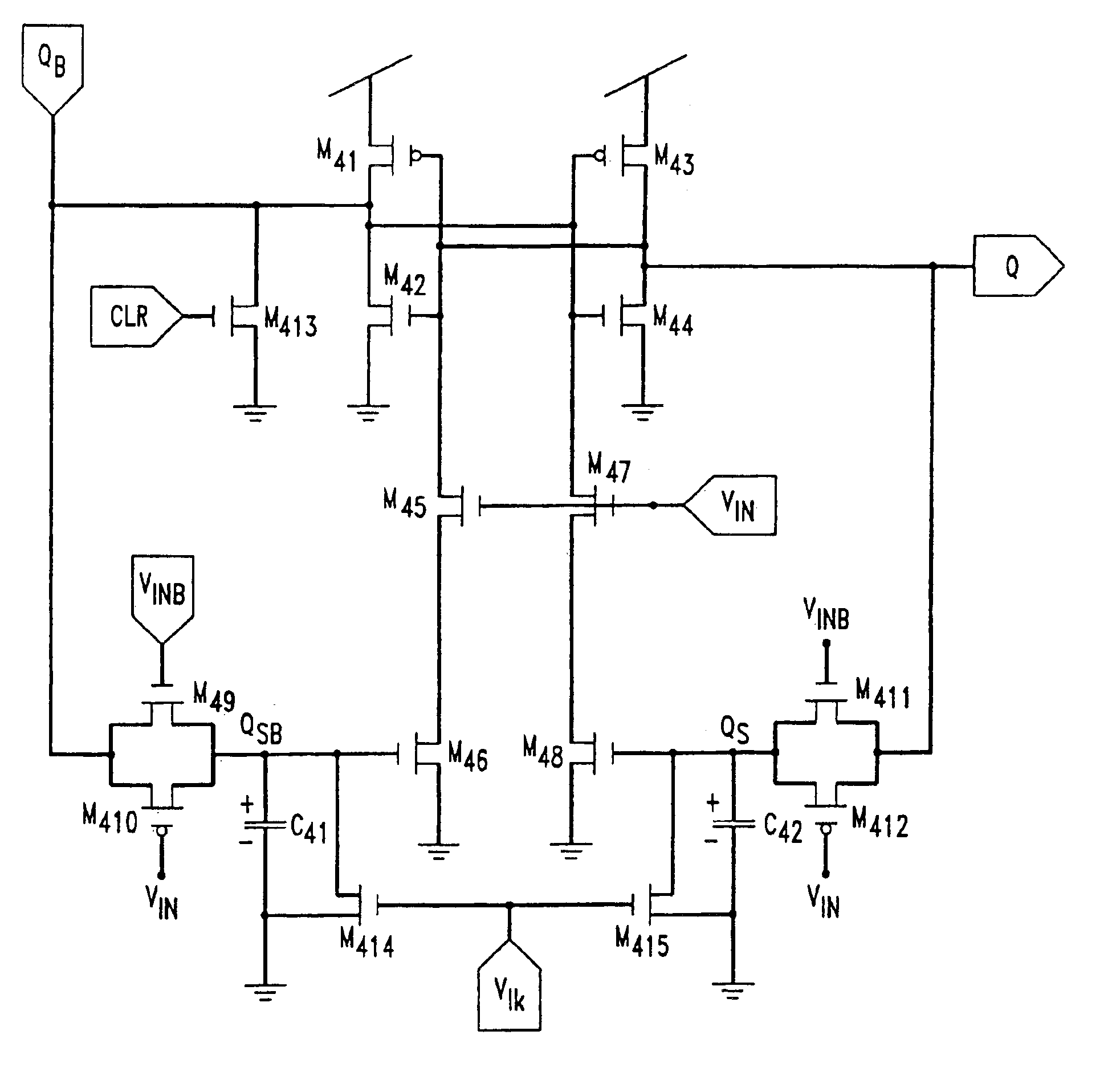
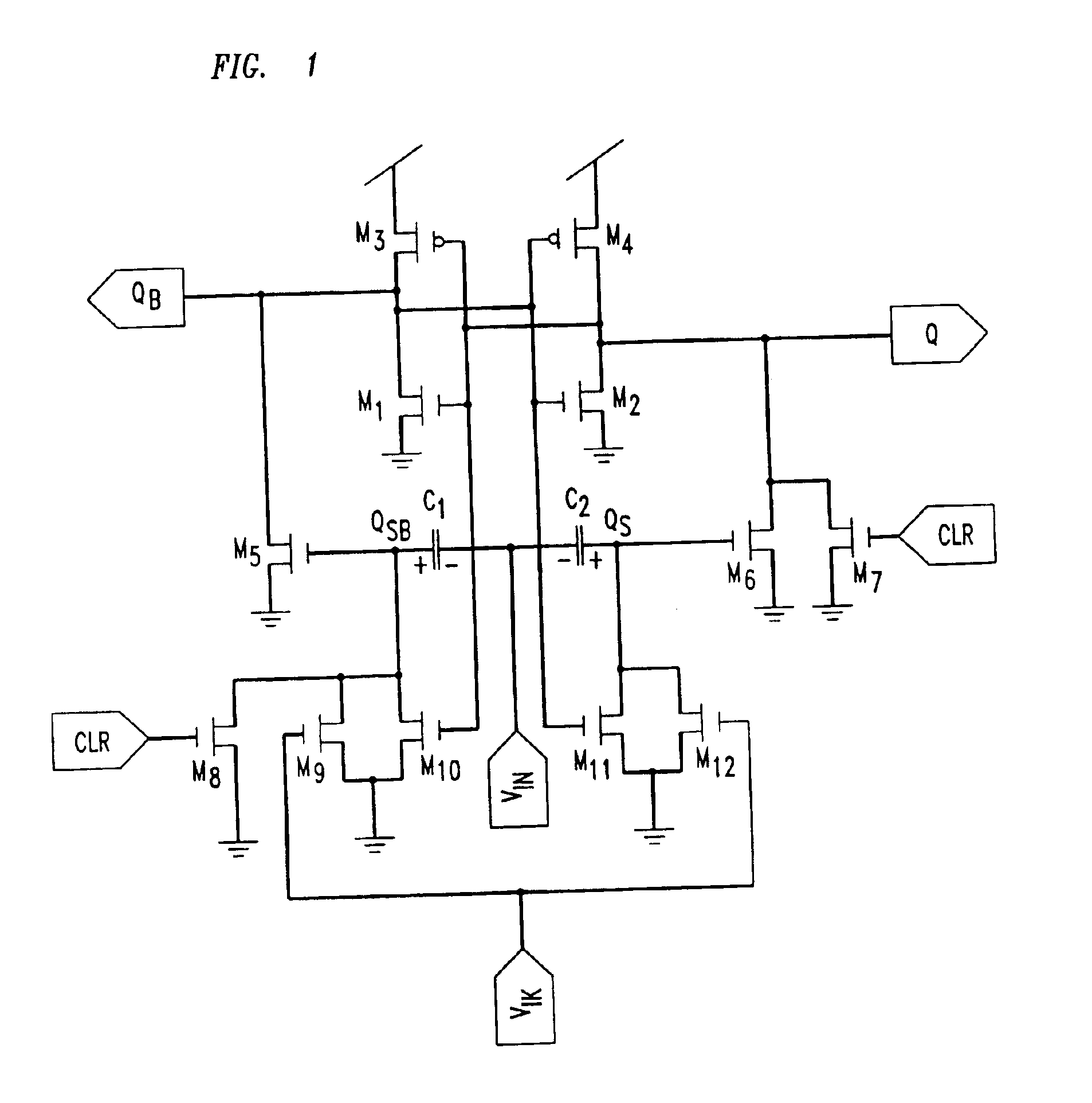
[0016]FIG. 1 is a circuit diagram of a first illustrative embodiment based on the present inventive teachings. In FIG. 1 and elsewhere in the present detailed description, transistors Mi and capacitors Cx, for all i and x, are of standard design suitable for manufacture in accordance with a variety of standard processes. Advantageously, CMOS MOSFET designs are employed, but any of PMOS, NMOS, or a combination of these and other types of devices may be employed to advantage in particular contexts. In keeping with standard practice, illustrative p-channel devices (such as M3) include a “bubble” on the gate, denoting a device that turns on as the gate is made more negative relative to the source. Likewise, the positive power supply is normally positioned at the top of diagrams, with negative voltages at the bottom. (Power supply voltages in circuit diagrams herein will be referred to as VDD, with ground being the reference voltage.) So, sources of p-channel devices are at the top, whil...


PUM


Abstract

An edge-triggered flip-flop circuit in which a pair of capacitors are alternately charged and discharged to voltages approximating supply rail values and, in combination of with a small number of switches, present high or low impedance paths for input signal transitions of a predetermined polarity to trigger state changes. In an alternative embodiment large switching capacitors are avoided in a circuit that employs a pair of pass-transistor configurations to connect respective capacitors to output terminals of a bistable device. The voltages on the capacitors track the corresponding bistable device output voltages when the input signal is in a given state (illustratively low), and store the value of the corresponding voltage when turned off by the (illustratively high) other state of the input signal. Then, the voltage on the capacitors and the selected input signal transition is used to effectively trigger a transition in the bistable device.

Description

[0001]This application is a divisional application Ser. No. 09 / 407,535, filed on Sep. 29, 1999 now U.S. Pat. No. 6,621,319, the entire contents of which are hereby incorporated by reference and for which priority is claimed under 35 U.S.C. § 120.RELATED APPLICATIONS[0002]Subject matter relating to that of the present application is presented in U.S. Patent applications filed on the same day as this application: “Spiking Neuron Circuit” by R. Sarpeshkar; and “Spike-Triggered Asynchronous Finite State Machine,” by R. Herrera and R. Sarpeshkar. These applications are assigned to the assignee of the present application and are hereby incorporated by reference in the present application.FIELD OF THE INVENTION[0003]The present invention relates to electronic circuits, and, more particularly to bistable circuits for use as digital building block circuits used in electronic systems. Still more particularly, embodiments of the present invention relate to edge-triggered toggle flip-flop circu...

Claims


Application Information

Patent Timeline
Patent Type & Authority Patents(United States)
IPC IPC(8): H03K3/356H03K3/00
CPCH03K3/356113
Inventor HERRERA, RUBENSARPESHKAR, RAHUL
Owner AVAGO TECH WIRELESS IP SINGAPORE PTE
Why Eureka
Try Eureka