Monitoring and control of watercraft propulsion efficiency

a technology of propulsion efficiency and monitoring and control, which is applied in the direction of navigation instruments, vessel construction, instruments, etc., can solve the problems of propeller not moving water, slipping, and simply increasing the power of the propeller does not automatically translate proportionally into increasing the speed, so as to reduce the cavitation, improve the speed, and improve the speed

Inactive Publication Date: 2005-04-19
MOTSENBOCKER MARVIN A
View PDF17 Cites 11 Cited by
  • Summary
  • Abstract
  • Description
  • Claims
  • Application Information

AI Technical Summary

Benefits of technology

[0010]One object of the invention is to provide a continuous optical readout in real time of propeller slip over a wide range of boat speeds. This readout allows the boat operator to optimize electric motor power for more efficient travel even at low speeds where cavitation is not a major concern.
[0011]Another object of the invention is to alert the boat operator to an adverse condition such as low speed cavitation, high

Problems solved by technology

Unfortunately, merely increasing power to a propeller does not automatically translate proportionally into increased speed.
In the real world a propeller does not move water at the ideal rate but will experience some slip.
Some propeller slip is necessary for a propeller to accelerate a boat and represents inefficiency in moving the boat.
The inefficiency of the drive system at different speeds is not obvious to the user and for the most part is not appreciated unless the user actually see or hears the wasted energy from extreme positive slip as cavitation.
During cavitation, much of the propeller energy is lost in the formation of bubbles and some is lost as heat.
Although each of the patents cited above addresses cavitation in internal combustion engine drive watercraft the general problem of overall efficiency at different pr

Method used


Image

  • Monitoring and control of watercraft propulsion efficiency
  • Monitoring and control of watercraft propulsion efficiency
  • Monitoring and control of watercraft propulsion efficiency

Examples


example 1

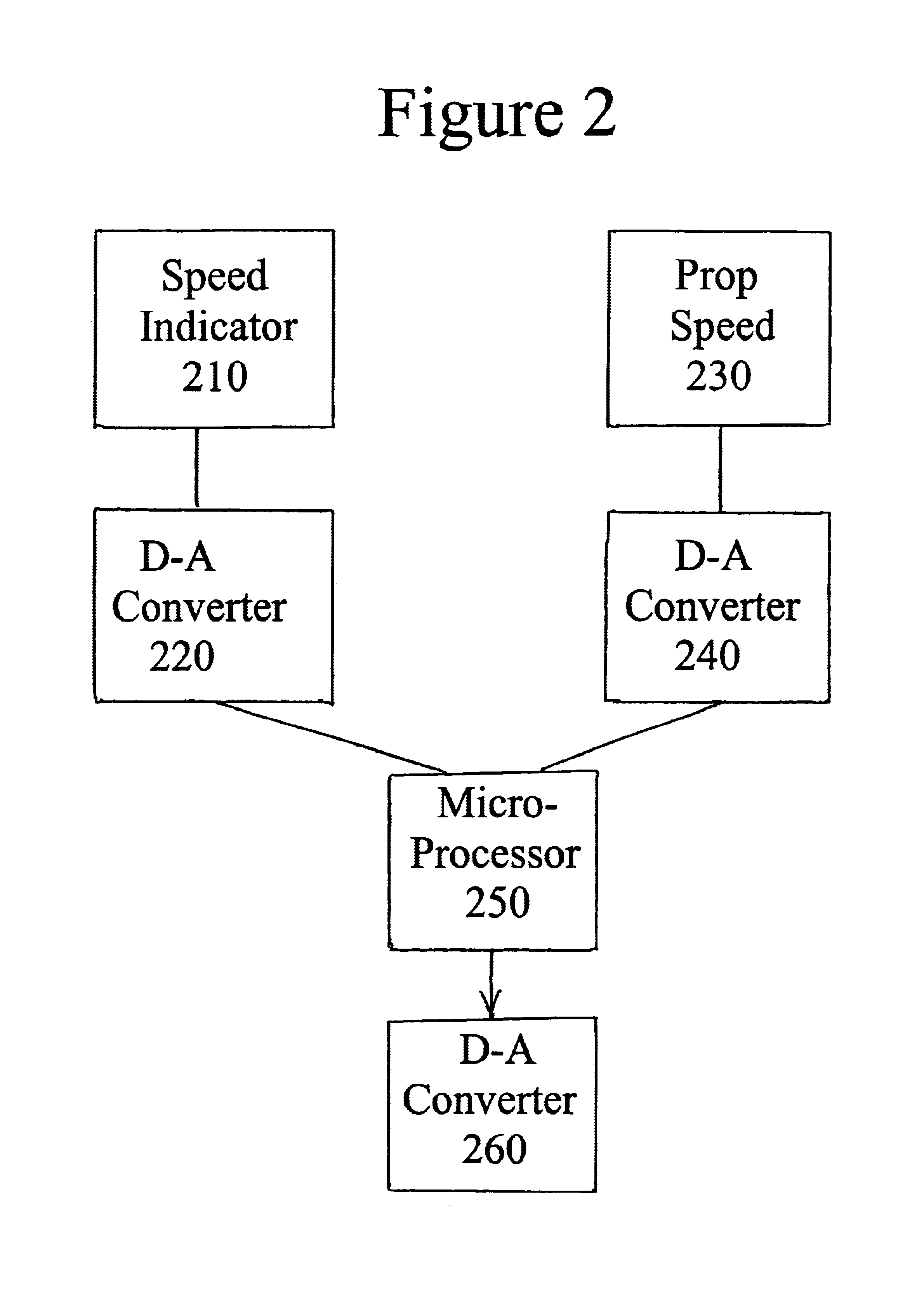
[0060]This example shows the generation of boat speed and propeller speed signals, and use of those signals to generate a ratio slip signal. An analog propeller speed signal is obtained by a hall effect sensor purchased from Westberg Mfg. Inc. of Sonoma, Calif. wired to a LM2917 chip. An analog boat speed signal is obtained by a hall-effect paddle wheel speed sensor attached to the trailing edge of a skis from a Maruta watercraft manufactured by ElectroCruise Boats of Homosassa Springs, Fla. The two analog signals are adjusted to provide equal ranges for each by setting amplification and zero level as needed. The adjusted signals are then converted to log form using operational amplifiers as log amplifiers with transistor junctions in their feedback loops. The log outputs are fed into a difference amplifier circuit, which subtracts the boat speed log signal from the propeller log signal to generate the ratio slip signal. The ratio signal represents both negative apparent slip (when ...

example 2

[0061]This example shows the generation of a positive slip indicator signal. Two adjusted analog signals are formed as described in Example 1. The boat speed signal is subtracted from the propeller speed signal by a difference amplifier and this difference is used as an absolute slip signal for an analog slip meter. In a second experiment the difference signal is fed into a log amplifier to decrease the dynamic range of the signal to allow more convenient use of an analog indicating device.

example 3

[0062]This example shows generation of a cavitation signal. The signal output from example 1 is fed into a comparator and a reference signal corresponding to a high slip value equivalent to a slip of 100% is fed into the comparator. The comparator output is used to signal a chime. When the signal output of example 1 exceeds the reference signal the comparator turns on the chime, alerting the watercraft operator of excessive slip condition. In a separate experiment the comparator output is further processed to indicate whether the high slip condition occurs during low watercraft speed or at cruising speed. In this latter experiment a boat speed signal is fed to a threshold level detector that outputs a signal when the boat speed achieves half maximum speed. That signal is used to select a second piezo electric buzzer that signals when high (above 100%) slip occurs at higher speed condition.


PUM


Abstract

Readout devices and controls are provided that alert the user to unusual propeller slip conditions. Embodiments of the invention incorporate some signal processing to account for a progressively greater slip at lower watercraft speeds. Thus, the invention provides simple information that tells the user if a boat propeller combination is being operated suboptimally, without requiring the knowledge and use of multiple slip figures for differing boat speeds. The invention allows greater economy of operation, automatic anticavitation control and can alert the watercraft operator to unusual conditions such as anchor down, propeller up other situations that affect propeller loading.

Description

REFERENCE TO RELATED APPLICATIONS[0001]This application claims benefit from application No. 60 / 296,754, filed Jun. 11, 2001.BACKGROUND OF THE INVENTION[0002]Electric motors increasingly are being used in watercraft because of their greater efficiencies compared to fossil fueled motors. Other advantages prompting use of electric motors include smaller weight, greater reliability and elimination of smoke and fumes when using an electric motor, particularly in combination with all electric battery systems. Typically, a source of electric power, such as a lead acid battery bank or fuel cell, is connected to the electric motor and an electronic valve such as a PMW (pulse modulated width) controller is used to modulate motor power. The motor output is coupled to a propeller either directly through a shaft coupling, or indirectly, through a belt, gear or other mechanism. In practice, a boat operator increases boat speed merely by increasing motor power. To slow down, the operator decreases...

Claims


Application Information

Patent Timeline
IPC IPC(8): B63H1/18B63H1/28B63H1/00
CPCB63H1/28B63H1/18
Inventor MOTSENBOCKER, MARVIN A.
Owner MOTSENBOCKER MARVIN A
Why Eureka
Try Eureka