Projector with array LED matrix light source

a technology of array led matrix and light source, which is applied in the direction of discharge tube luminescnet screens, instruments, television systems, etc., can solve the problems of high energy consumption and overheating of traditional filament-type projection lamps, and achieve the effects of simple structure, higher light intensity, and more energy-saving

Inactive Publication Date: 2005-04-19
CHENG KUNG CAPITAL
View PDF11 Cites 34 Cited by
  • Summary
  • Abstract
  • Description
  • Claims
  • Application Information

AI Technical Summary

Benefits of technology

[0006]An object of this invention is to provide a light source for a projector which is more energy efficient. Another object of this invention is to provide a light source for a projector which is simpler in structure. Still anoth

Problems solved by technology

From the standpoint the energy efficiency, environmental protection and desirability for higher light inte

Method used


Image

  • Projector with array LED matrix light source
  • Projector with array LED matrix light source
  • Projector with array LED matrix light source

Examples


first embodiment

[0031]FIG. 4 shows LED assembly of the light source cell in the matrix array. The blue LEDs 20B, the green LEDs 20G and the red LEDs 20R are mounted through respective bottom contacts (electrodes) on separate rows of metal rods 21B, 21G and 21R. The top electrodes of the green LEDs 20G and red LEDs are wire-bonded through wires 24 to metal rod 21 parallel to and interposed between rods 21R and 21G. The top electrodes of the blue LEDs 20B are wire-bonded through wires 24 to metal rod 22 below and parallel the metal rod 21B. The metal rods 21, 22, 21R, 21G, 211B are isolated from each other. Thus the row of red LEDs 20R and the row of the green LEDs 20G can be individually selected to be lighted with only three rows 21, 21R and 21G. The assembly is incorporated in a light source cell of the LED matrix.

second embodiment

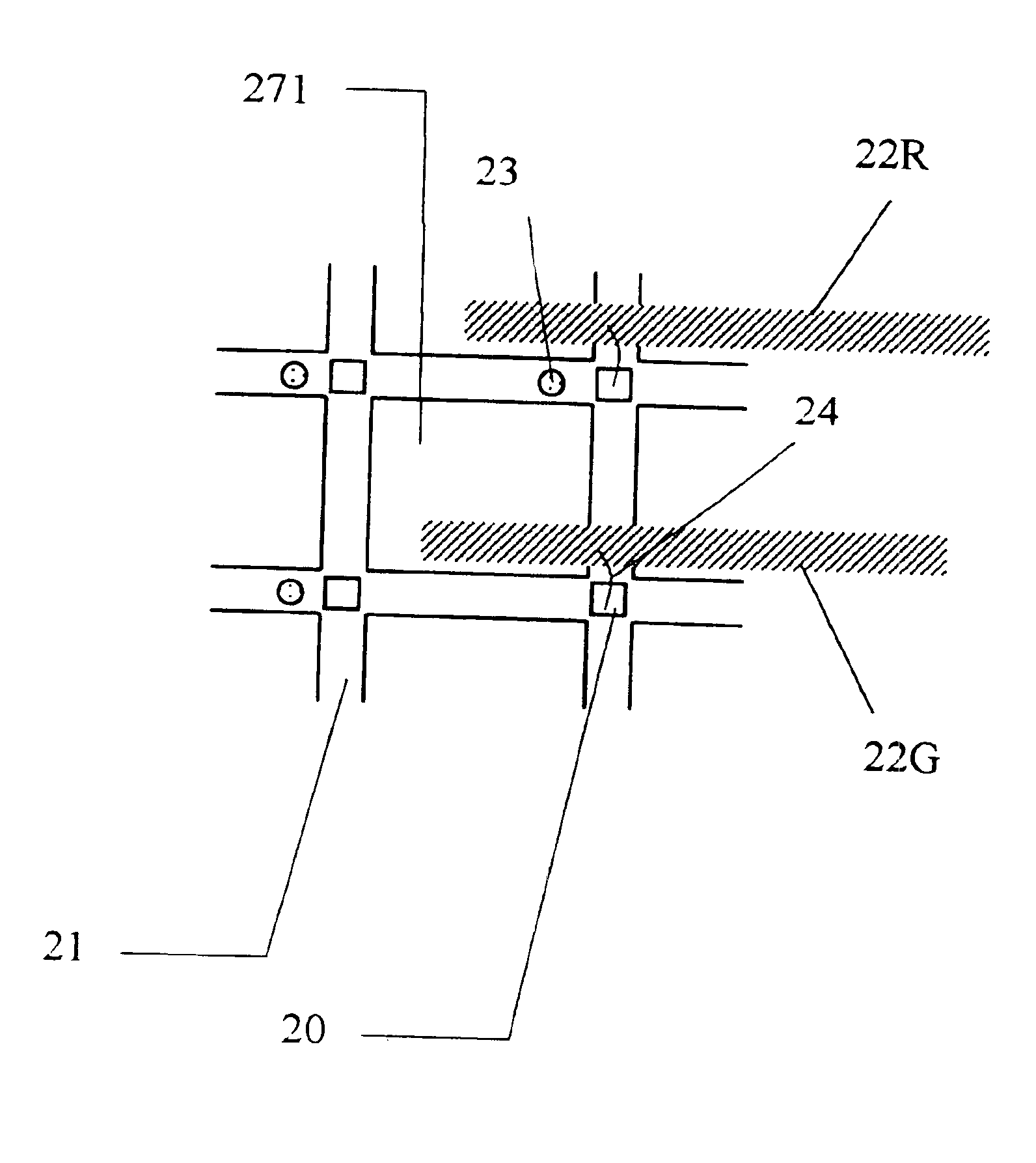
[0032]FIG. 5 shows the LED assembly of the light source cell. The LED chip 20 is mounted with bottom electrode on a metal grid 21. The top electrodes of the LEDs are individually wire-bonded with wire 24 to respective red metal rod 22R and green metal rod 22G.

[0033]When single color light is to be displayed, all the LED can be of the same color chip. If different color is to be displayed, the three primary color LED chips should be mixed. For instance, all the LEDs coupled to the metal rod 22R can use the same color LED chips, such as red LED chips. All the LED chips coupled to the metal rod 22G can be of the same green LED chips. In the same manner, a set of blue LED chips can be added and coupled to a blue metal rod. By controlling the liquid crystal plates electronically, the emitted light can be selected and varied. The metal rods 22G, 22R and the metal grid are isolated from each other by means of insulator 23. The through holes 271 are for increasing air circulation to remove ...

third embodiment

[0034]FIG. 6 show the LED assembly of the light source cell. The difference from FIG. 5, is that LED chips 201, 202 are doubly mounted at each cross point and wire-bonded by wires 24 to respective metal rods 22G and 22R for the purpose of increasing the light intensity. The windows 271 between the metal grid are for increasing air circulation to remove heat.


PUM


Abstract

A light emitting diode matrix array is used as the light source of a picture projection system. Each cell of the LED matrix array has an assembly of one or more red, green and blue LEDs with metal lead structures to individually energize these LEDs. The lights emitted from the LED assembly is transmitted through one or more programmable liquid crystal plate or digital micro-mirror device to control the light transmission, and then merged together for projection as a pixel onto a screen.

Description

BACKGROUND OF THE INVENTION[0001](1) Field of the Invention[0002]This invention relates to light source of a projector, in particular to the use of light emitting diode matrix as light source. This patent application is co-pending with U.S. patent application Ser. No. 09 / 982,371, filed Oct. 19, 2001; now U.S. Pat. No. 6,650,048.[0003](2) Brief Description of Related Art[0004]FIG. 1 shows a prior-art three-gun projector unit 100 for color display. A projector lamp 10 projects a full color light beam L to a prism 11, which splits the light into a blue light beam B, green light beam G and red light beam R. The split light beams B, G, R pass through three transmissive liquid crystal display plates 12B, 12G, 12R, respectively, which control the timing and the amount of transmission through each plate. The transmitted light beams transmit past three corresponding lens 15B, 15G, 15R and project onto a screen 18 to display a full color picture. By changing the transmission through each liqu...

Claims


Application Information

Patent Timeline
IPC IPC(8): G09G3/34H04N9/31
CPCH04N9/3197H04N9/315G09G2310/0235
Inventor WU, JIAHN-CHANG
Owner CHENG KUNG CAPITAL
Why Eureka
Try Eureka