Method and device for production, extraction and delivery of mist with ultrafine droplets

a technology of ultrafine droplets and production methods, applied in the direction of atomized substances, dental surgery, lighting and heating apparatus, etc., can solve the problems of not achieving optimal aerosol formation or separation, no special separation device is implemented, and the residence time of the mist and the carrier in the misting chamber is too short, so as to improve the function or throughput, improve the effect of mist ejection, and improve the flow of carrier gas

Inactive Publication Date: 2005-04-26
NANOMIST SYST
View PDF12 Cites 55 Cited by
  • Summary
  • Abstract
  • Description
  • Claims
  • Application Information

AI Technical Summary

Benefits of technology

[0018]With respect to the outlet for the aerosol mist, various configurations may be suitable. For instance, an outlet may be oriented tangentially to the fountain column on the upper or lower portions of the container. Alternatively, an outlet could be situated at the top of the extractor container, or a vortex finder tube could be centrally located in the mist-generating container for upward discharge of the fine aerosol mist. Further, the outlet could be connected to a member of conically converging diameter to assist in concentrating the aerosolized mist for delivery.
[0019]In other examples of alternative configurations, multiple inlets tangentially situated to the fountain column could be provided to improve carrier gas flow, or multiple outlets could be provided for improved mist ejection. Additionally, arrangements may be provided that use multiple atomizers or transducers to improve function or throughput.

Problems solved by technology

However, the mists generated from these prior high throughput units generally comprise both small and larger droplets, mostly greater than several microns in size due to the methods utilized in extraction and transport of the mist formed in the mist generating unit.
However, the direct air current impinging on the water fountain in these humidifiers further forces the mist coming out of the humidifier to contain large proportions of the more coarse water droplets found in the center of the mist fountain.
Moreover, residence time of the mist and carrier in the misting chamber is too short and not favorable for stable aerosol formation.
No special separation device is implemented for separation of coarser mist droplets not large enough to fall back into the fountain.
Again, the device has not means of achieving optimum aerosol formation or separation of coarser droplets, and airflow directly impinging from above on the mist formation region would negatively affect optimum aerosol formation and separation.
Thus, the transport and post-processing of the mist would cause significant loss of mist by coalescence and condensation into liquids.
As a result, these mists created by prior mist generators include many shortcomings that are disadvantageous for humidification and other applications.
Additionally, maximum throughput reportedly generated by prior methods of has been limited to about 0.25 liter per minute (Lpm) and uses generating apparatus of unacceptably large physical size and high cost.
These large droplets are obstructed by physical objects and condense and drop out and, thus, do not display gas-like flow behavior, which causes crack and crevices and other areas to remain unaffected by the mist.
Dropping out and condensation causes the amount of liquid needed in applications to be very high, which also leads to leaving the areas treated damp because of deposited liquid causing collateral damage in the area treated.

Method used


Image

  • Method and device for production, extraction and delivery of mist with ultrafine droplets
  • Method and device for production, extraction and delivery of mist with ultrafine droplets
  • Method and device for production, extraction and delivery of mist with ultrafine droplets

Examples


Embodiment Construction

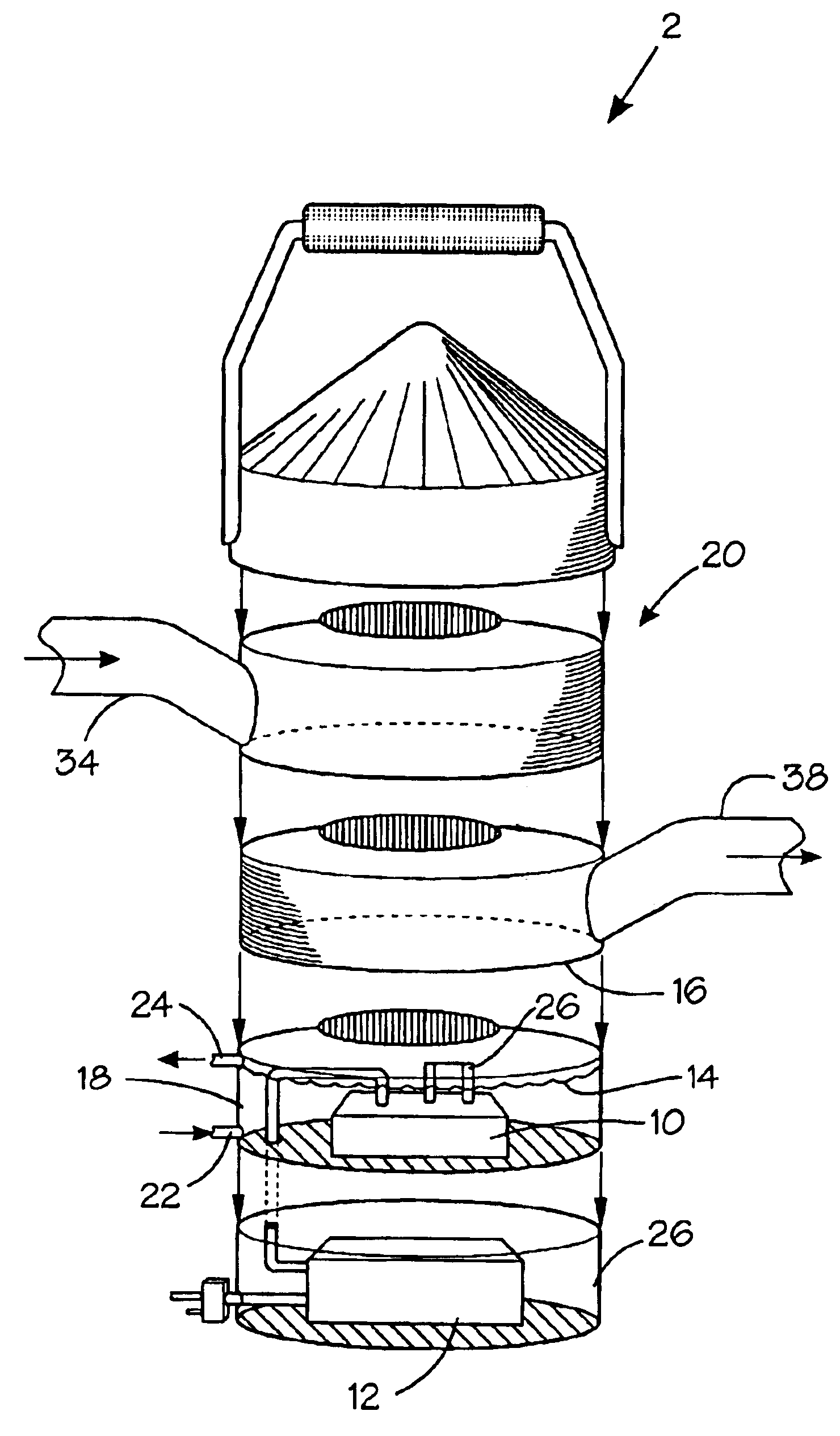
[0033]The present invention and its various embodiments are described in terms of mist generation or droplet formation using an array of transducers, uniquely defined configuration of airflow into the mist generating location, aerosol formation, stability of mist, transport of aerosol, classification of mist, and configuration of mist outflow.

[0034]In a first embodiment, the present invention provides one or more piezoelectric transducers 10 connected to a power supply 12, usually an external driver. The piezoelectric transducers generate a mist from a liquid contained in a reservoir 14 at the base 16 of the unit. The reservoir and liquid may suitably remain at ambient pressure and at ambient temperature. Usually, the transducers are submerged in the liquid in the reservoir with the crystal submerged about 1-2 inches below the liquid surface or otherwise arranged in physical communication with the solution. The reservoir is contained within the chamber walls 18 of the device, and th...


PUM

PropertyMeasurementUnit
diameteraaaaaaaaaa
diameteraaaaaaaaaa
sizeaaaaaaaaaa

Abstract

The present invention provides a method and device for production, extraction and delivery of an aerosol mist with ultrafine droplets. A high frequency wave generating device or other process generates very small particles or droplets from a reservoir of liquid or material to be atomized. A helical flow of a carrier gas medium such as air is directed into a container and creates a high throughput aerosol of air and fine droplets. The aerosol is delivered through a suitable outlet such as by deflecting the aerosol upwards and providing a tube centrally situated with respect to the helical flow such that the aerosol will discharge through the tube in high quantity of throughput and high quality of stable aerosol of very fine mist droplets. The methods described utilize in-situ extraction of fine mist droplets using helical flow behavior as opposed to forced convection ejection of mist or inertial separation of droplets by separators.

Description

PRIORITY CLAIM[0001]The present application claims priority of U.S. provisional patent application No. 60 / 365,870 filed on Mar. 20, 2002 and U.S. provisional patent application No. 60 / 323,399 filed on Sep. 19, 2001.BACKGROUND OF THE INVENTION[0002]1. Field of the Invention[0003]The present invention relates to the creation, extraction and high throughput delivery of very fine mist for humidification, fire suppression, blast mitigation or other chemical applications. In particular, the invention pertains to generating a mist containing very fine droplets at ambient pressure from a reservoir of water or liquid, and, then, effectively aerosolizing very fine droplets from the mist using swirl or helical flow behavior for delivery with sufficiently high throughput for effective application.[0004]2. Description of the Prior Art[0005]Previously, ultrasonic transducer devices have been used in small-scale mist generation units to generate mists for familiar purposes such as medical inhalers...

Claims


Application Information

Patent Timeline
Patent Type & Authority Patents(United States)
IPC IPC(8): A61L2/22A62C39/00A61L9/14B05B17/04B05B7/10B05B7/02B05B17/06B05B7/00F22B1/28A62C2/00A62C5/00A62C31/00A62C99/00B05B1/08B05B1/34B05B3/14
CPCA61L2/22A61L9/145A62C5/00A62C5/008B05B17/0615A62C99/0072B05B7/0012B05B7/10A62C31/00
Inventor ADIGA, KAYYANI C.ADIGA, RAJANIHATCHER, JR., ROBERT F.
Owner NANOMIST SYST
Why Eureka
Try Eureka