
Thermal process station with heated lid

a technology of thermal processing station and lid, which is applied in the direction of charging supports, lighting and heating apparatus, furnaces, etc., can solve the problems of adversely affecting the performance of baked photoresist, and achieve the effect of improving the thermal uniformity of workpieces

Active Publication Date: 2005-04-26
TEL EPION
View PDF22 Cites 379 Cited by
  • Summary
  • Abstract
  • Description
  • Claims
  • Application Information

AI Technical Summary

Benefits of technology

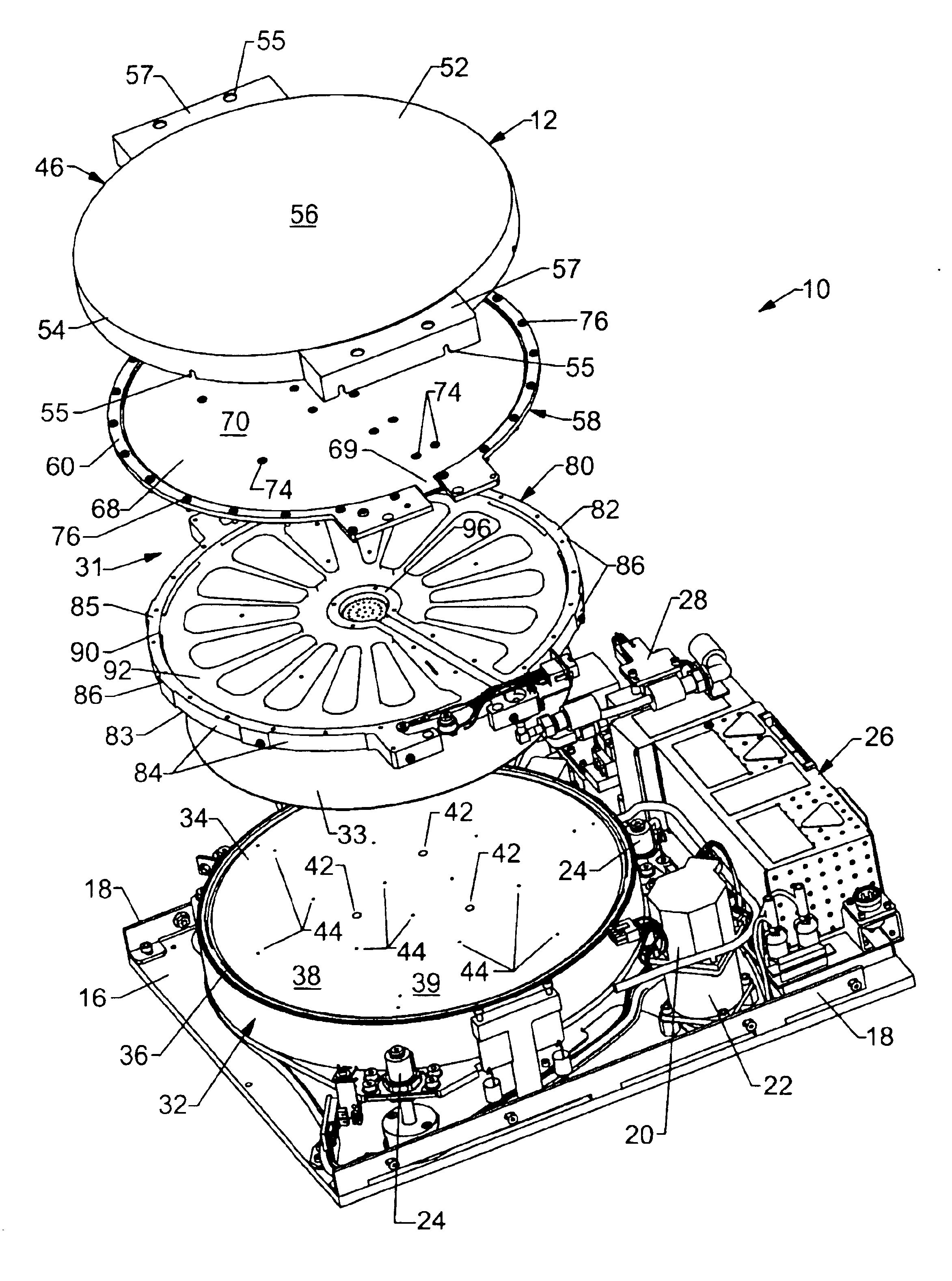
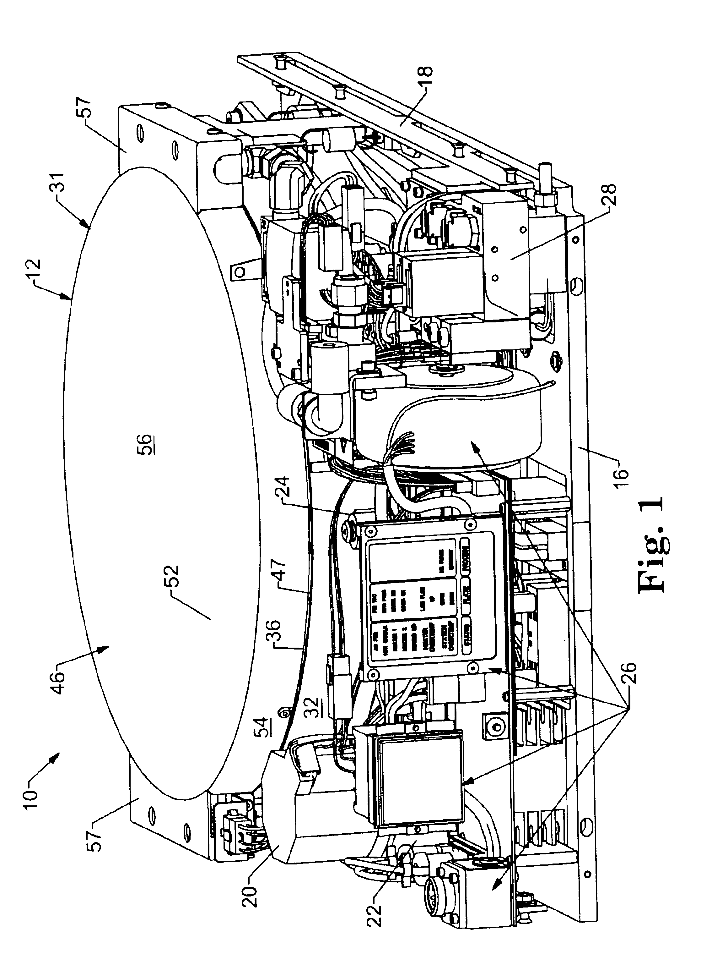
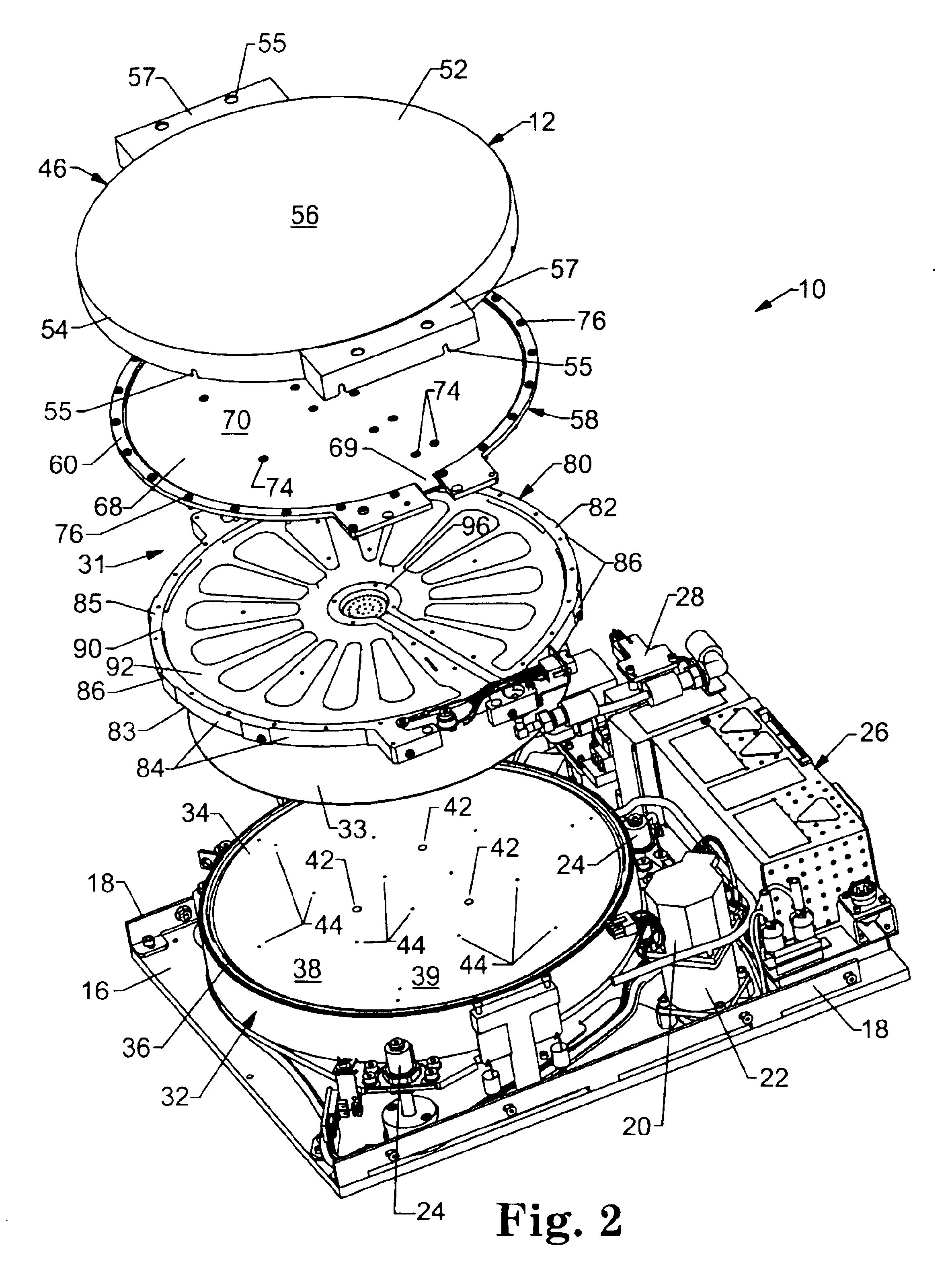
[0010]The present invention provides methods and apparatuses that improve the temperature uniformity of a workpiece being processed on a heated platen. The present invention is based upon enclosing the heated platen in a housing incorporating an additional heat source that uniformly outputs thermal energy into the process chamber in which the heated platen is positioned. In preferred embodiments, this heat source is positioned in the lid of the housing. It is additionally preferred that the heated lid includes features that provide a gas flow path to introduce to and / or purge gas from the process chamber. In terms of photoresist performance, the improved thermal uniformity provided by using such an additional heat source in the housing, e.g., in the lid, offers improved line width control and line uniformity across a wafer.
[0015]In still another aspect of the present invention, a method is provided of improving the thermal uniformity of a workpiece during a thermal treatment. The method includes the steps of 1) providing a first heat source have a first heating face, 2) providing a second heat source having a second heating face, wherein the first and second heating faces are opposed to each other, and 3) positioning the workpiece between the first and second, opposed heating faces during at least a portion of the thermal treatment.

Problems solved by technology

Too much temperature variation over the wafer surface area can adversely impact the performance of the baked photoresist, and hence the quality of the resultant devices.
Moreover, the heating device was used to prevent condensation of the vapors inside the processing chamber and was not used to enhance thermal uniformity of the wafer being processed inside the chamber.

Method used


Image

  • Thermal process station with heated lid
  • Thermal process station with heated lid
  • Thermal process station with heated lid

Examples


Embodiment Construction

[0023]The embodiments of the present invention described below are not intended to be exhaustive or to limit the invention to the precise forms disclosed in the following detailed description. Rather the embodiments are chosen and described so that others skilled in the art may appreciate and understand the principles and practices of the present invention.

[0024]The principles of the present invention may be incorporated into a wide variety of different kinds of heating units in which it is desired to uniformly thermally process one or more microelectronic workpieces at one or more stages in the manufacture of microelectronic devices. For example, the principles of the present invention may be readily incorporated into any kind of priming or baking station used in the course of forming patterned or unpatterned photoresist layers on such workpieces.

[0025]For purposes of illustration, the present invention will be further exemplified in connection with a preferred thermal processing s...


PUM

PropertyMeasurementUnit
Heataaaaaaaaaa

Abstract

Methods and apparatuses to improve the temperature uniformity of a workpiece being processed on a heated platen of a thermal processing station. A heated platen is enclosed in a housing incorporating an additional heat source that uniformly outputs thermal energy into the process chamber in which the heated platen is positioned. In preferred embodiments, this heat source is positioned in the lid of the housing. It is additionally preferred that the heated lid includes features that provide a gas flow path to introduce to and / or purge gas from the process chamber. In terms of photoresist performance, the improved thermal uniformity provided by using such an additional heat source in the housing, e.g., in the lid, offers improved line width control and line uniformity across a wafer.

Description

CROSS-REFERENCE TO RELATED APPLICATIONS[0001]The present non-provisional Application claims the benefit of commonly assigned provisional Application having Ser. No. 60 / 409,561, filed on Sep. 10, 2002, and entitled THERMAL PROCESS STATION WITH HEATED LID, which Application is incorporated herein by reference in its entirety.FIELD OF THE INVENTION[0002]The present invention relates to thermal processing stations used particularly in the manufacture of microelectronic devices and being of the type incorporating a heated platen on which a workpiece is thermally processed. More specifically, the present invention relates to such stations that incorporate a heated platen and an additional heat source.BACKGROUND OF THE INVENTION[0003]The manufacture of many products requires precise control over temperature and temperature changes. For example, the manufacture of microelectronic devices, such as integrated circuits, flat panel displays, thin film heads, and the like, involves applying a la...

Claims


Application Information

Patent Timeline
IPC IPC(8): F27D1/18H05B3/68C23C16/00F27B17/00H01LH01L21/00H01L21/027
CPCF27B17/0025H01L21/67126H01L21/67109
Inventor NGUYEN, VUONG P.SIMS, RICHARD E.ZHU, XIAOGUANG
Owner TEL EPION
Learn More