Electrochemical system for analyzing performance and properties of electrolytic solutions

Inactive Publication Date: 2005-04-26
LANDAU UZIEL
View PDF11 Cites 29 Cited by
  • Summary
  • Abstract
  • Description
  • Claims
  • Application Information

AI Technical Summary

Problems solved by technology

Such alloy data cannot be generated by the corresponding current/potential scanning experiment.
Also, unlike in the device disclosed herein, conventional scan

Method used


Image

  • Electrochemical system for analyzing performance and properties of electrolytic solutions
  • Electrochemical system for analyzing performance and properties of electrolytic solutions
  • Electrochemical system for analyzing performance and properties of electrolytic solutions

Examples


example 1

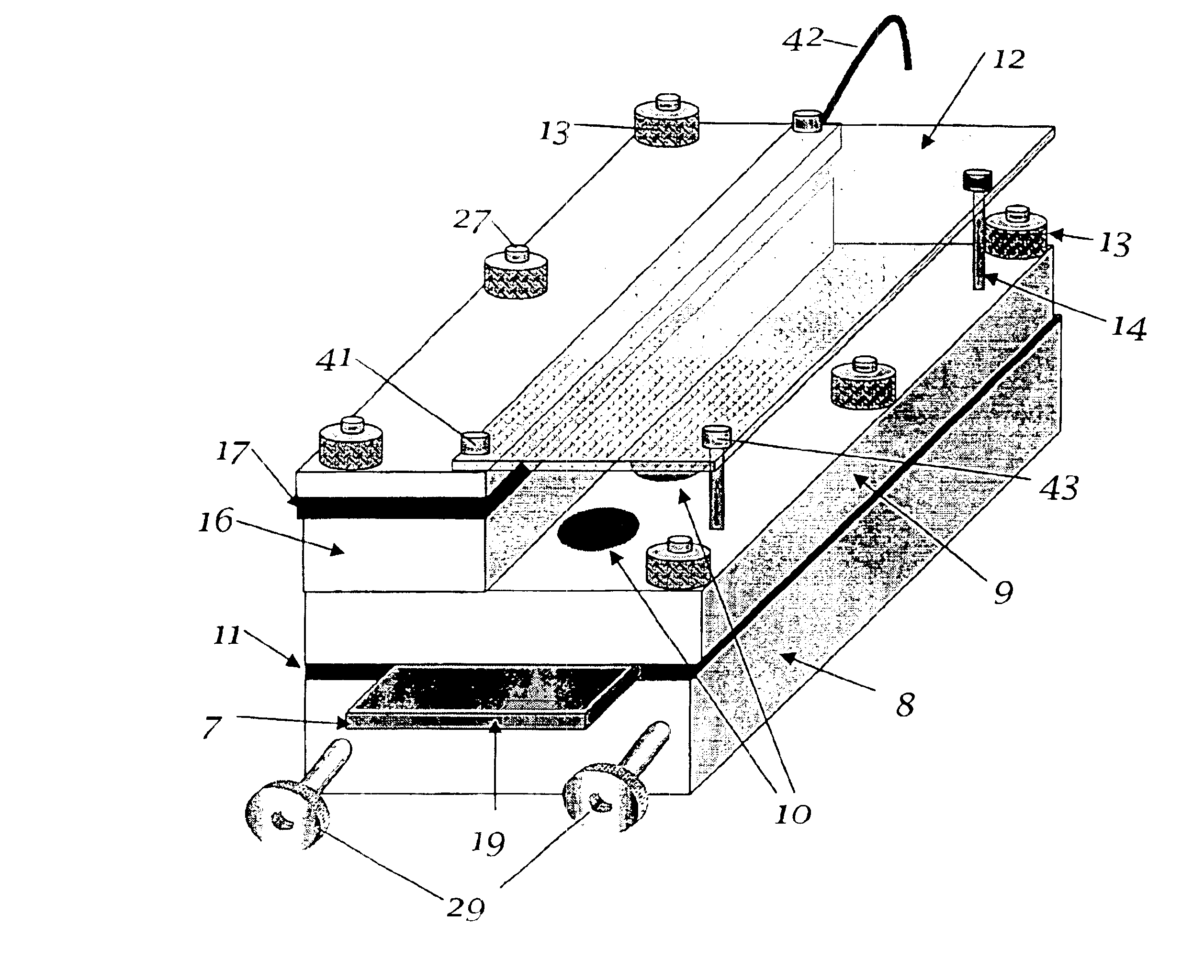
[0063]FIG. 3A is a schematic drawing of a device that incorporates facets of the invention disclosed herein. FIG. 3A shows an overall view, FIG. 3B is a partially transparent view of the device showing some internal features of the cell. FIG. 3C shows the cover of the cell in an upside-down view, revealing the separate contacts and the cavities. FIG. 3D is a view of the bottom part of the cell with the top removed, showing the plated segmented substrate. FIG. 3E shows a schematic top view of the plated segmented cathode, and FIG. 3F is a cross-section (not to scale) of same substrate. FIGS. 3G and 3H are cross-sections of the device. The specific device described herein is about 2 inches wide, 5 inches long and about 1.5 inches high. It is understood that different sizes may be applied. Following is a detailed description of the device.

[0064]The device consists of two major parts as shown in detail in FIGS. 3C and 3D: a base (8) shown in detail in FIG. 3D, and a cover (9), shown in ...

example 2

[0074]Another cell and electrode configuration that can be used advantageously when incorporating elements of the invention disclosed herein, is a segmented rotating disk electrode (RDE), as shown schematically (60) in FIG. 5A, or a rotating segmented disk electrode surrounded by a ring electrode (62), as shown schematically in FIG. 5B. An insulating ring (64) separates the two. The ring electrode may serve as the reference electrode, a co-planar anode, or another auxiliary electrode whose potential is scanned and is used for analyzing products or reactants of the electrochemical reaction [Ref. 5]. The segments can be pie-shaped at the bottom of the rotating shaft (60), as shown in FIG. 5A. This configuration works similarly to that discussed in example 1, however, it can provide also additional transport data. As shown by Levich [Ref. 6], the rotating disk provides a uniform and easily calculable boundary layer thickness (or mass transport coefficient) that depends on the inverse s...

example 3

[0075]The device disclosed herein can also be configured as a cylinder, as shown schematically in FIG. 6A and FIG. 6B. This configuration can be used similarly to the ones discussed above e.g., Example 1. It has, however, a number of advantages: it can be rotated to incorporate the effects of transport, as in example 2, it can be designed in a compact form, to be used with small volumes, and furthermore, if configured as a very small diameter, it can present low transport resistance, since the radial diffusion flux is inversely proportional to the radius. Because of the electrode curvature, it can account for and simulate the effect of curvature on the deposit, e.g., incorporate effects of curvature on stress, and adhesion. The latter may be particularly important, because often deposits that show marginal adhesion to a flat substrate may adhere satisfactorily to a curved one. The segmental electrodes (66) can be stacked one on top of the other as shown in FIG. 6A or the cylinder ca...


PUM

PropertyMeasurementUnit
Timeaaaaaaaaaa
Thicknessaaaaaaaaaa
Dielectric polarization enthalpyaaaaaaaaaa

Abstract

The invention relates to the analysis of the performance and properties of electrochemical processes, and specifically, to electrolytic solutions and electrode processes. The invention discloses a device and a method for obtaining qualitative and quantitative information for the kinetics of the electrode reactions, the transport processes, the thermodynamic properties of the electrochemical processes taking place in the cell. When a deposition reaction takes place, the device provides also valuable information about the relationship between the current density and deposit properties including but not limited to the deposit color, luster, and other aspects of its appearance. The device disclosed herein typically is comprised of a multiplicity of cathodic or anodic regions where one or more electrochemical reactions take place simultaneously, but at a different rate. From the precisely measured segmental currents one can obtain among other process properties: (1) An accurate relationship between the deposit appearance and the current density. This relationship can be used for process diagnostics, troubleshooting, control of concentrations, pH, and additives and contaminants and for optimizing the operating conditions, including the voltage, current, and circulation rate. (2) Quantitative determination of important process parameters including but not limited to, kinetics (e.g., exchange current density, cathodic and anodic transfer coefficients), transport (e.g. conductivity), and thermodynamics (e.g., standard potential). A particularly attractive application of the process is for the quantitative and qualitative processes of alloys plating and for the determination of the relationship between the current efficiency and the applied current density.

Description

RELATED APPLICATIONS[0001]This is a Continuation of U.S. application Ser. No. 10 / 791,169 which in turn is a Continuation-in-Part application of U.S. application Ser. No. 10 / 267,505 now abandoned, having a filing date of Mar. 2, 2004 and Oct. 9, 2002 respectively.References Cited[0002]U.S. Patent Documents2149344March 1939Hull204 / 153.2760928August 1956Ceresa204 / 434.2801963August 1957Hull et al.204 / 434.2859166November 1958Grigger204 / DIG.3121053February 1964Hull, Jr. et al.204 / 434.3215609November 1965Chapdelaine204 / 434.3278410October 1966Nelson204 / 290.3281338October 1966Leary et al.204 / 290.3356597December 1967Schmidt204 / 434.3616287October 1971Draghicescu et al.204 / DIG.4102770July 1978Moriarty et al.204 / 212.4252027February 1981Ogden et al. 73 / 826.4605626August 1986Beck204 / 403.5,228,976July 1993Abys et. al.5,413,692May 1995Abys et al.6,113,771September 2000Landau et. al.Other References[0003]1. Cell-Design©, Software for computer-aided-design of electrochemical cells, L-Chem Inc, 13909 L...

Claims


Application Information

Patent Timeline
IPC IPC(8): C25D21/12
CPCC25D21/12
Inventor LANDAU, UZIEL
Owner LANDAU UZIEL
Why Eureka
Try Eureka