Radial polarization-rotating optical arrangement and microlithographic projection exposure system incorporating said arrangement

a technology of rotational polarization and exposure system, which is applied in the field of optical arrangement, can solve the problems of high light loss, low efficiency, and low efficiency, and achieve the effect of low loss, low scattering light, and high apertur

Inactive Publication Date: 2005-04-26
CARL ZEISS SMT GMBH
View PDF29 Cites 49 Cited by
  • Summary
  • Abstract
  • Description
  • Claims
  • Application Information

AI Technical Summary

Benefits of technology

[0013]It is an object of the invention to provide an optical arrangement which permits a homogeneous coupling of light into optical boundary surfaces with high aperture and with l...

Problems solved by technology

However, a loss of efficiency is accepted because in each case, the locally perpendicular polarized light component is intensely reflected.
However, it is not disclosed how a complete polarization of the transmitted light is achieved.
Both polarizers are polarization filters, that is, they lead to high light loss and are suitable only for a...

Method used


Image

  • Radial polarization-rotating optical arrangement and microlithographic projection exposure system incorporating said arrangement
  • Radial polarization-rotating optical arrangement and microlithographic projection exposure system incorporating said arrangement
  • Radial polarization-rotating optical arrangement and microlithographic projection exposure system incorporating said arrangement

Examples


Embodiment Construction

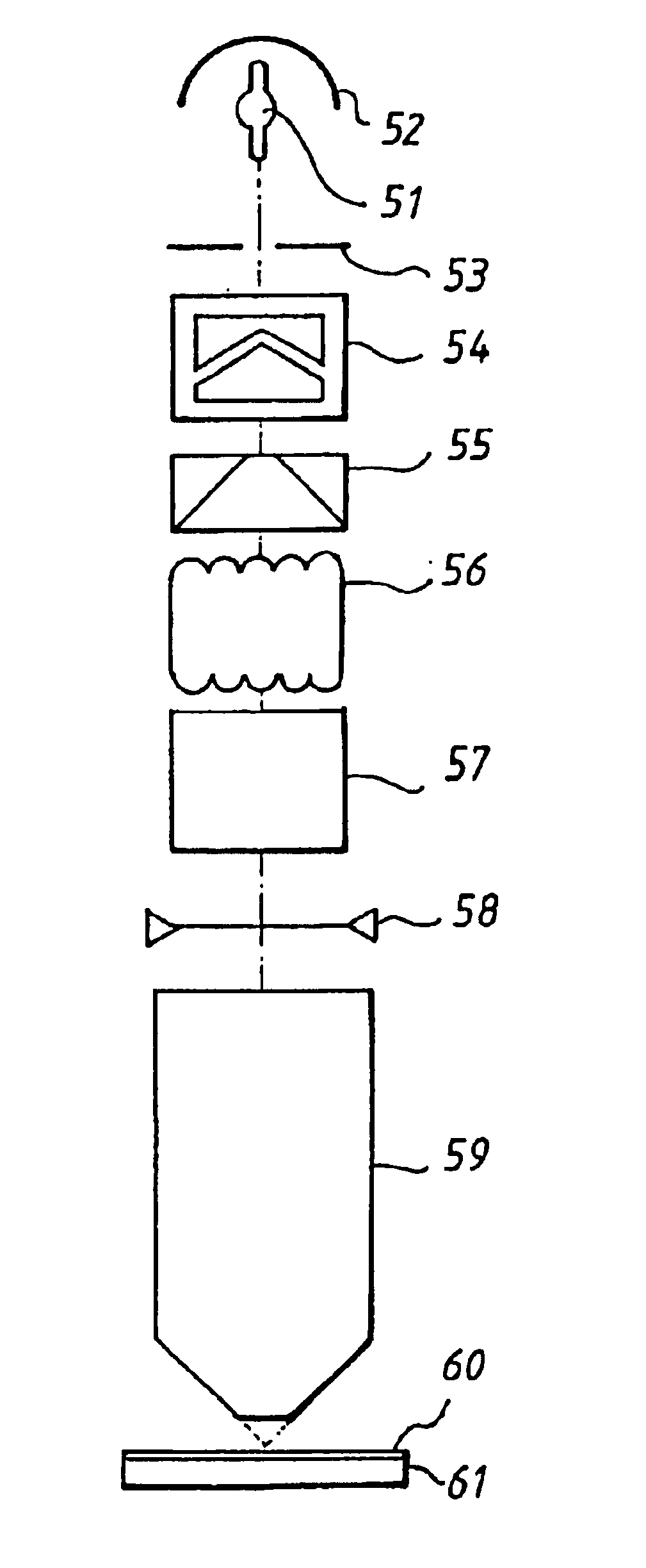
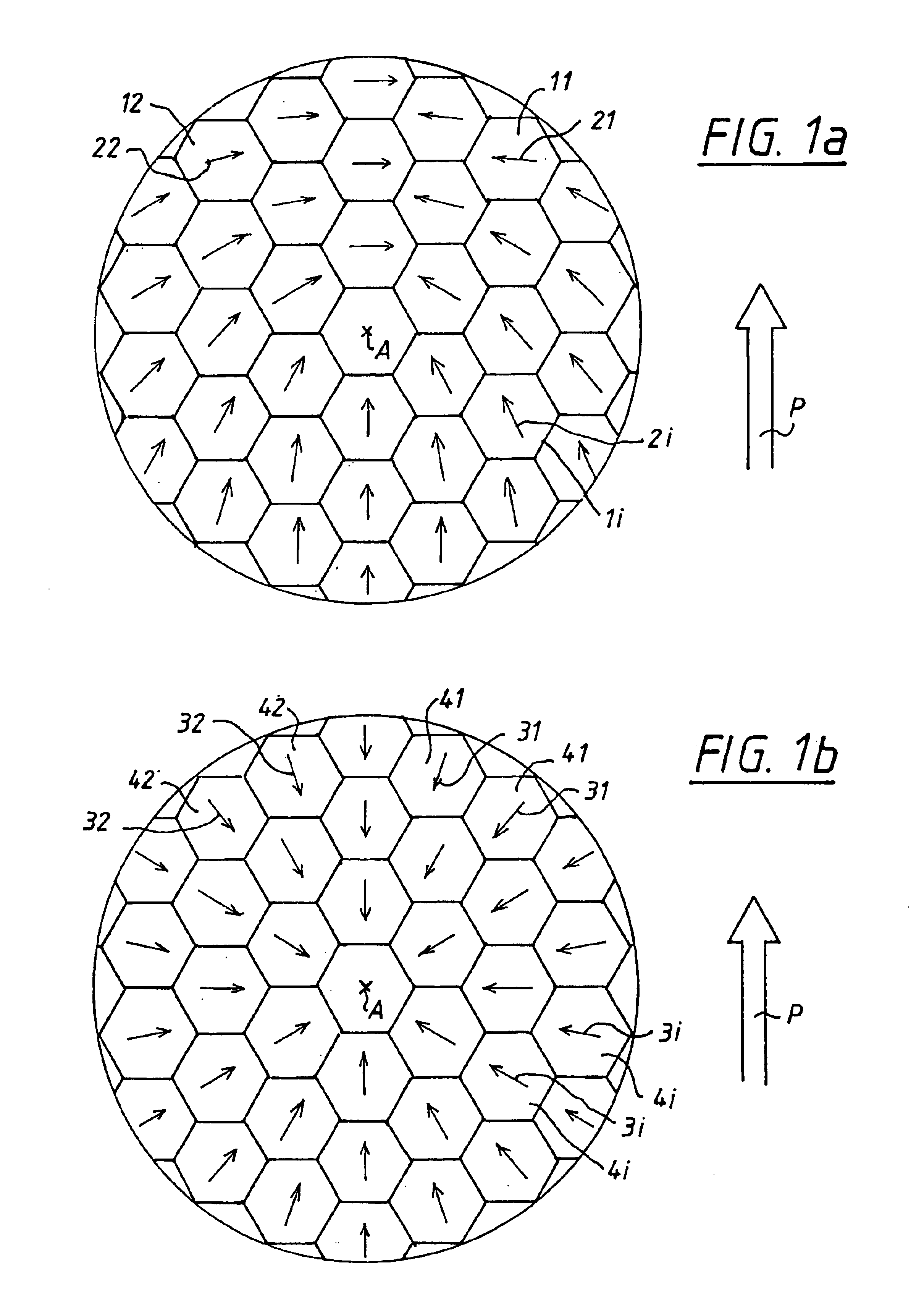
[0039]A polarization-rotating arrangement according to the invention is shown in FIGS. 1a and 1b as it is suitable especially in combination with a honeycomb condenser for the conversion of linearly polarized light. This arrangement is especially suited for lasers as a light source. The beam cross section is subdivided into a multiplicity of facets (11, 12, 1i) which is, in each case, made of a half-wave plate of birefringent material. Each facet 1i corresponds to a honeycomb element of the honeycomb condenser. The facets 1i are preferably cemented to the honeycomb or placed in wringing contact therewith. For extreme radiation loads, the facets can be separately held and coated to prevent reflection. The honeycomb condensers conventional for microlithographic projection exposure systems have about 102 honeycomb elements and the number of the facets is the same.

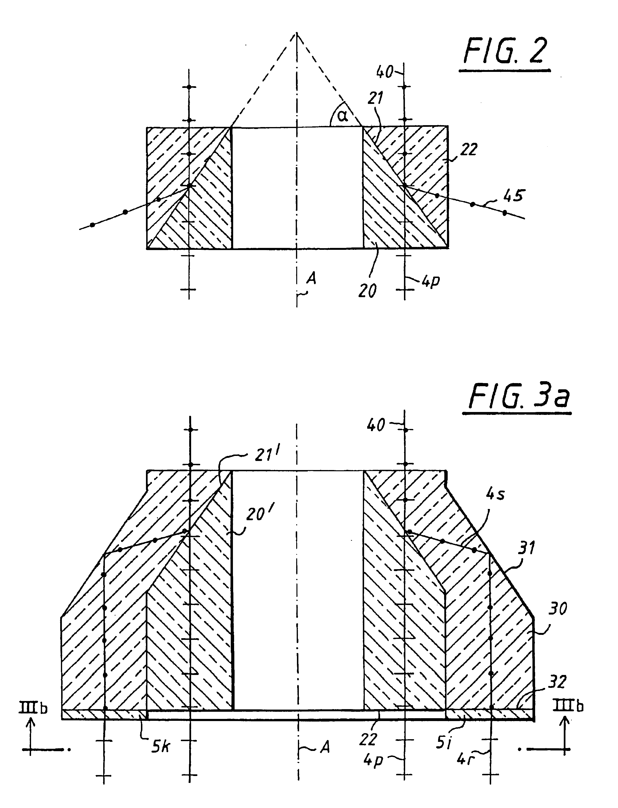
[0040]The main axes (21, 22, 2i) of the facets (11, 1i) are each aligned in the direction of the angle bisector between the ...


PUM


Abstract

An optical arrangement is disclosed wherein an entering beam is converted into an exiting beam having a total cross section of light which is linearly polarized essentially in the radial direction by rotation. For this purpose, rasters of half-wave plates (41, 42, 4i), a combination of birefringent quarter-wave plate 420 and a circular plate 430 is suggested in combination with a conical polarizer 21′. This arrangement is preferably utilized in the illumination portion of a microlithographic projection exposure system. It is important that the arrangement be mounted behind all asymmetric or polarizing component elements 103a.

Description

[0001]This is a divisional of patent appication Ser. No. 09 / 730,778 filed Dec. 7, 2000 now U.S. Pat. No. 6,392,800, which is a divisional of patent application Ser. No. 09 / 352,408, filed Jul. 14, 1999, now U.S. Pat. No. 6,191,880 B1, which is a continuation of application Ser. No. 08 / 717,902, filed Sep. 23, 1996, now abandoned.FIELD OF THE INVENTION[0002]The invention relates to an optical arrangement which converts an entering light beam into an exiting light beam having light which is linearly polarized in the entire cross section essentially in radial direction.BACKGROUND OF THE INVENTION[0003]It is necessary to provide projection exposure systems with a very high numerical aperture in order to achieve the highest resolutions in microlithography. Light is coupled into the resist layer at very large angles. When this light is coupled in, the following occur: light losses because of reflection at the outer resist boundary layer and deterioration of the resolution because of lateral...

Claims


Application Information

Patent Timeline
IPC IPC(8): G02B5/30G02B27/28G03F7/20G02B19/00H01L21/027
CPCG02B5/3083G03F7/70566G02B27/283
Inventor SCHUSTER, KARL-HEINZ
Owner CARL ZEISS SMT GMBH
Why Eureka
Try Eureka