Anisotropic distributed feedback fiber laser sensor

a distributed feedback and fiber laser technology, applied in the field of fiberoptical measurement technology, can solve the problems of limited dynamic range, isotropic pressure, exclusive use, etc., and achieve the effect of enlarged dynamic range and very simple production

Inactive Publication Date: 2005-04-26
GE OIL & GAS UK LTD
View PDF8 Cites 86 Cited by
  • Summary
  • Abstract
  • Description
  • Claims
  • Application Information

AI Technical Summary

Benefits of technology

[0006]In a first aspect, the invention consists in a fiber laser sensor which has a DFB fiber laser with a laser-amplifying fiber and a fiber Bragg grating written in distributed fashion therein, a measurement quantity making it possible to induce a birefringence and beat frequency between modes of the laser-amplifying fiber and measurement means for determining the beat frequency being present, in which case, furthermore, the measurement quantity is an isotropic pressure acting radially on the laser-amplifying fiber or a chemical substance which can be added radially to the laser-amplifying fiber, and the laser-amplifying fiber has a nonrotationally symmetrical structure in such a way that the isotropic pressure or the chemical substance make it possible to induce the birefringence and beat frequency between one or a plurality of pairs of mo...

Problems solved by technology

What is disadvantageous is that use is made exclusively of two polarization modes, namely the spatial fundamental mode of the fiber with its two orthogonal linear polarization states, and an isotropic pressure cannot be measured.
Disadvantages of these sensors include the limited dynamic range, ...

Method used


Image

  • Anisotropic distributed feedback fiber laser sensor
  • Anisotropic distributed feedback fiber laser sensor
  • Anisotropic distributed feedback fiber laser sensor

Examples


Embodiment Construction

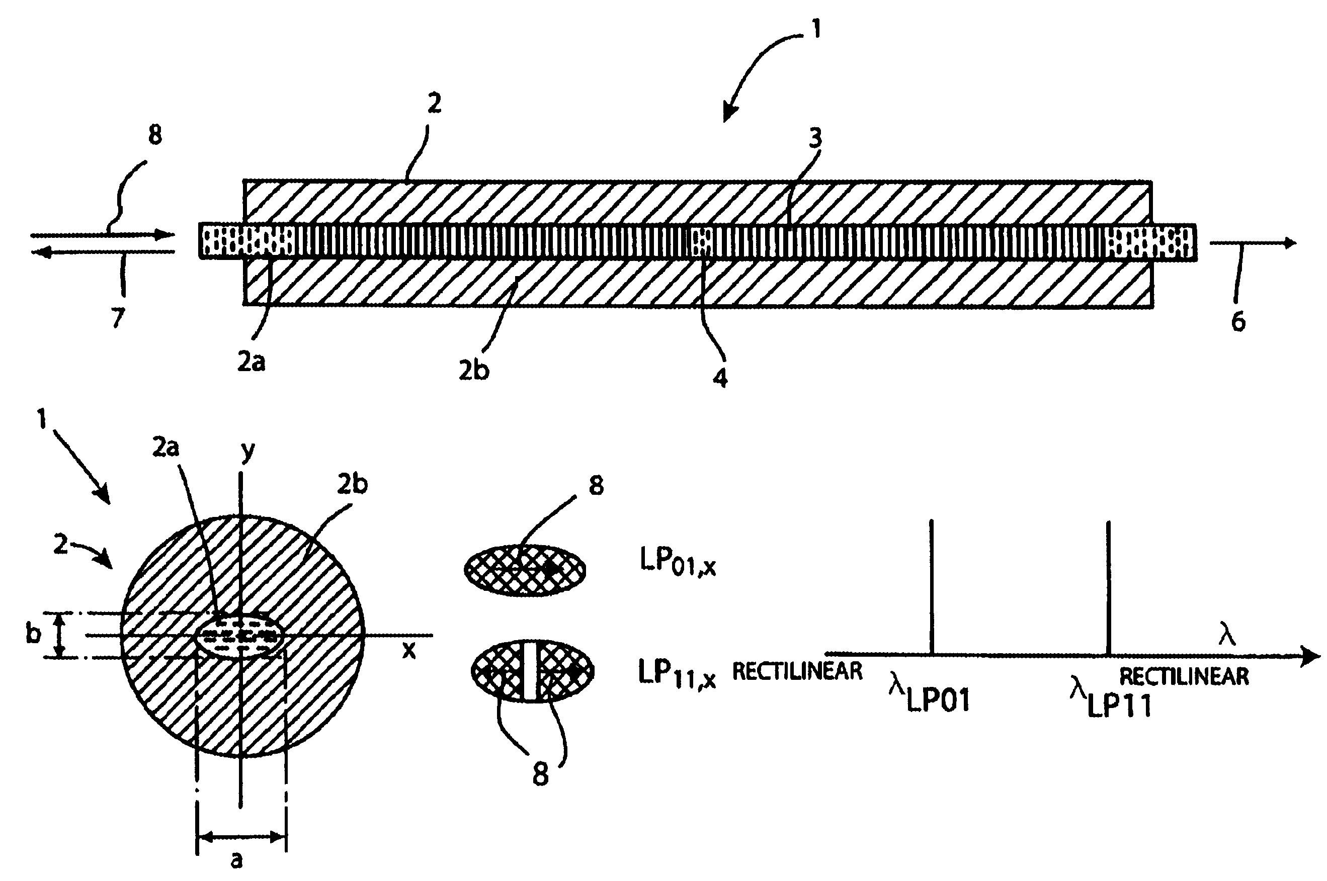
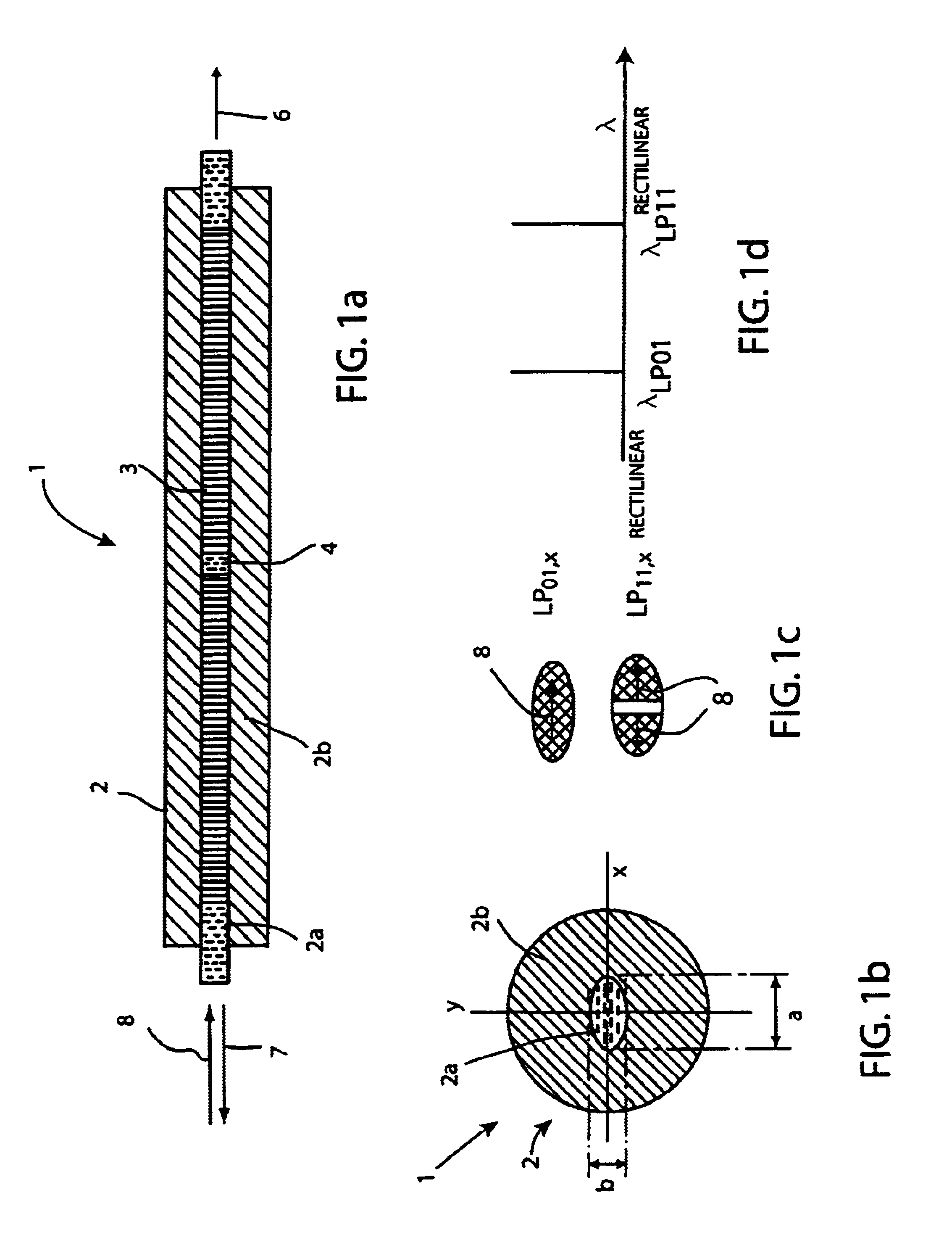
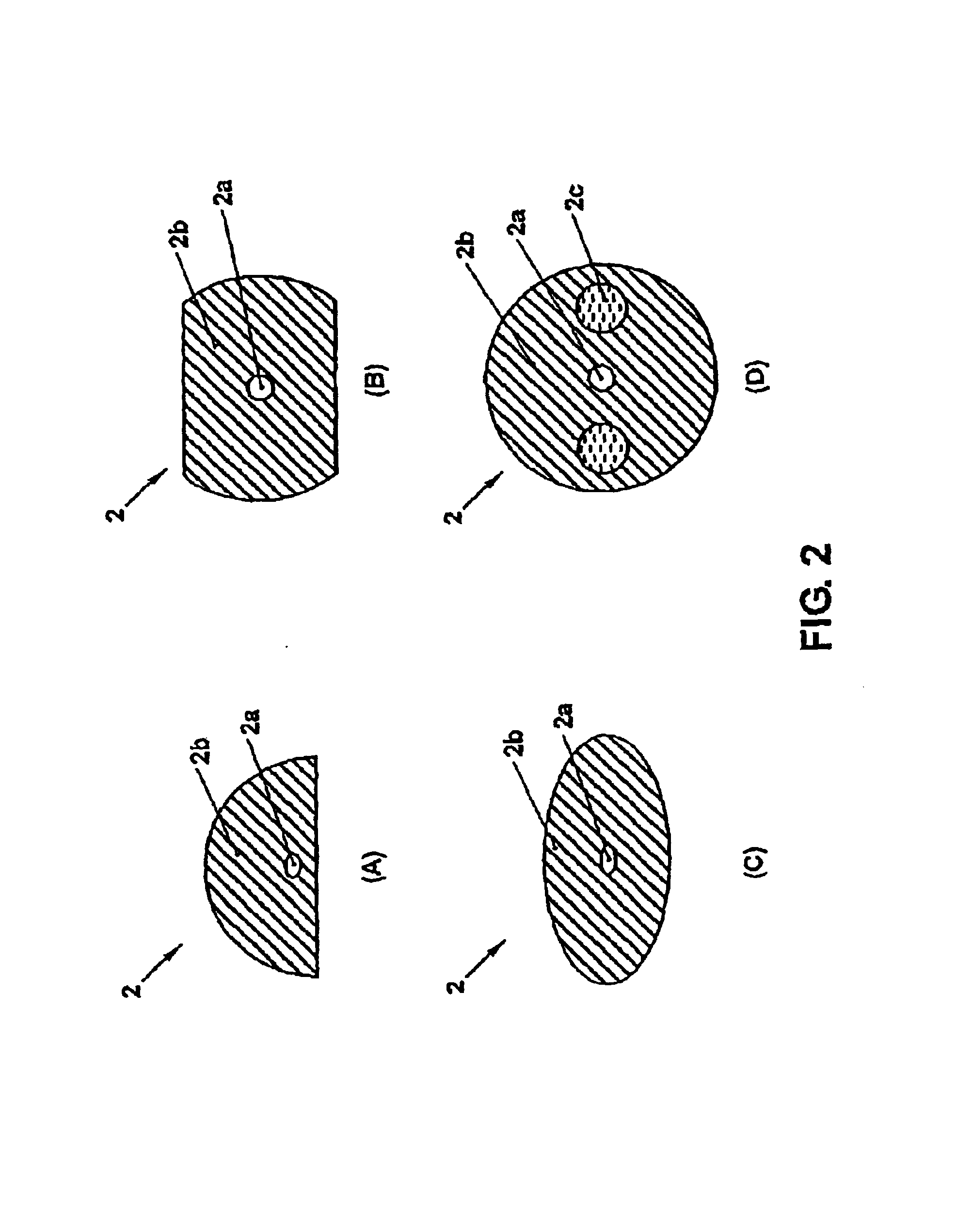
[0023]FIGS. 1a and 1b diagrammatically show the sensor part of a DFB fiber laser sensor 1 according to the invention. The laser 1 comprises a laser-amplifying fiber 2 for example having an elliptical core 2a and a round fiber cladding 2b. Linear polarization axes x, y are prescribed by the long principal axis a and the short principal axis b of the core 2a. The core 2a is doped with rare earth ions. The type of ions depends on the desired emission wavelength range of the laser 2. Erbium / ytterbium- or erbium-doped laser-amplifying fibers 2 are preferably used, whose emission lies in the range of between about 1520 nm and 1560 nm. Instead of being doped with erbium, the fiber can also be doped with other rare earth ions, e.g. praseodymium (emission around 1300 nm), neodymium (emission around 1060 mm) or thulium (emission around 810 nm). The wavelength of the pumping laser 13 (FIGS. 8, 9) must be adapted correspondingly.

[0024]The laser resonator 3 is formed by an individual Bragg grati...


PUM


Abstract

The invention relates to a DFB fiber laser sensor (1). A measurement quantity makes it possible to induce a linear birefringence between mode pairs of the laser-amplifying fiber (2) and to measure an associated beat frequency (Δν1, Δν2, Δν3). According to the invention, the laser-amplifying fiber (2) has a nonrotationally symmetrical structure, so that it is possible to detect isotropic pressures p, acoustic waves or chemical substances that can be added radially to the laser-amplifying fiber (2). In a second aspect of the invention, an emission wavelength range and parameters (a, b, ΔN) of the laser-amplifying fiber (2) and also a grating period L of the fiber Bragg grating resonator (3) are coordinated with one another such that at least two different spatial modes (LP01, LP11even, LP11odd, LP21even) are propagatable and it is possible to measure beat frequencies (Δν1, Δν2, Δν3) between oscillatory longitudinal laser modes assigned to them. Exemplary embodiments relate to: rotationally asymmetrical fiber types, a choice of special spatial modes (LP11odd, LP21even) and/or multiple fiber Bragg gratings (3) for reducing the beat frequencies (Δν1, Δν2, Δν3) below 100 GHz; and elimination of temperature influences e.g. by the detection of a plurality of beat frequencies (Δνa, Δνb, Δνc, Δνd) between different pairs of spatial modes (LP01, LP11even, LP11odd, LP21even) and/or polarization modes (X, Y).

Description

FIELD OF THE INVENTION[0001]The present invention relates to the field of fiber-optical measurement technology. It is based on a fiber laser sensor according to the preamble of the independent claims.BACKGROUND OF THE INVENTION[0002]In oil production it is necessary to monitor boreholes with regard to pressure and temperature. In the borehole, the liquid pressures can be up to approximately 100 MPa (1000 bar) and the temperatures can be up to above 200° C. Electrical sensors, such as e.g. piezoresistors, piezoelectric elements, capacitive probes or crystal resonators or optical pressure sensors, such as e.g. Fabry-Perot resonators, or elasto-optical sensors, are often used for pressure measurement up to approximately 170° C.[0003]U.S. Pat. No. 5,844,927 discloses a DFB fiber laser sensor in accordance with the preamble of the independent claims. What is disclosed is a laser-amplifying fiber with a distributed fiber Bragg grating resonator in which two orthogonally polarized modes ca...

Claims


Application Information

Patent Timeline
IPC IPC(8): G01L11/00G01L11/02
CPCG01L11/025
Inventor BOHNERT, KLAUS
Owner GE OIL & GAS UK LTD
Why Eureka
Try Eureka