Improving signal integrity in differential signal systems

a differential signal and signal integrity technology, applied in the field of high-speed signaling, can solve the problems of high-speed signaling, unable to achieve perfect impedance matching in practice, certain products failing radiofrequency emission control specifications, etc., and achieve the effect of improving the eye-opening characteristics of differential signals, differential signal quality improvement, and improving differential signal integrity

Inactive Publication Date: 2005-04-26
VALTRUS INNOVATIONS LTD
View PDF6 Cites 230 Cited by
  • Summary
  • Abstract
  • Description
  • Claims
  • Application Information

AI Technical Summary

Benefits of technology

[0010]Over-terminating the differential mode impedance of a differential transmission line, such as an INFINIBAND™ cable, at the receiving end, improves the differential signal integrity of the transmission line when variations can occur in impedance component (e.g., resistor) and transmission line characteristics. Over-terminatin

Problems solved by technology

High speed signaling, however, tends to generate noise.
This may cause certain products to fail radiofrequency emission control specifications established by the Federal Communications Commission (FCC) or other regulating agencies in various countries.
But, perfect impedance matchin

Method used


Image

  • Improving signal integrity in differential signal systems
  • Improving signal integrity in differential signal systems
  • Improving signal integrity in differential signal systems

Examples


Embodiment Construction

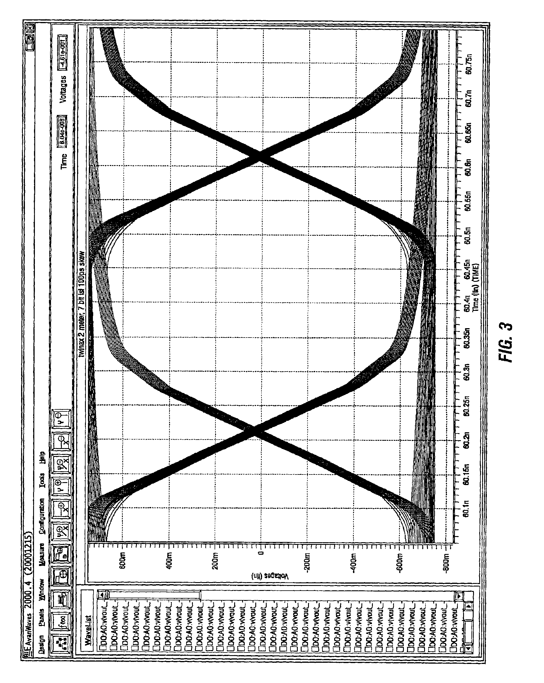
[0019]Embodiments of the present invention improve signal integrity and eye opening of high-speed transmission signals, which potentially lowers system cost and shortens the time-to-market of products.

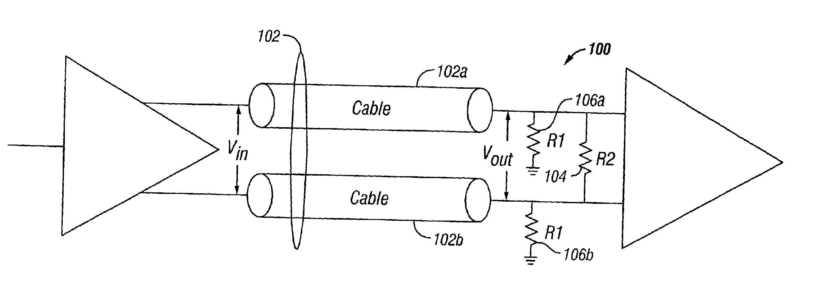
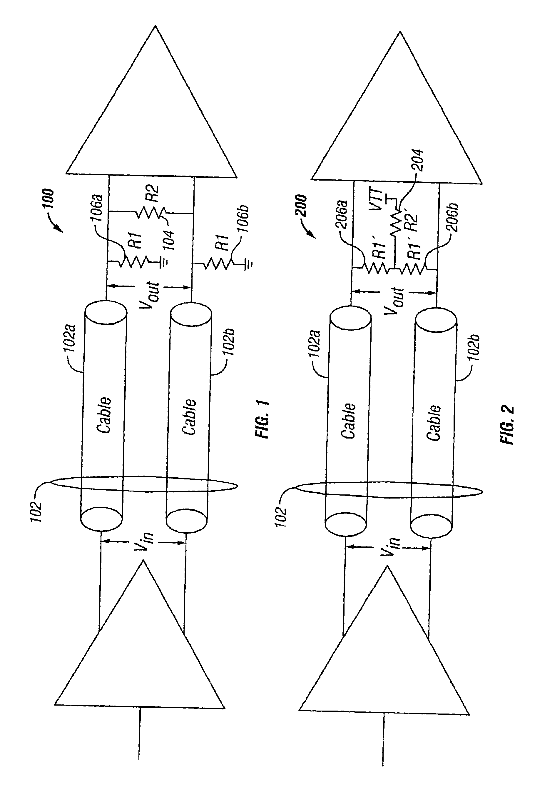
[0020]Although the INFINIBAND™ (“IB”) architecture is referred to herein, it should be understood that this is merely exemplary of a wide variety of high-speed system architectures in which the present invention can be employed. In the IB Architecture, the differential output impedance, Zd, is specified at 125 ohms maximum and 75 ohms minimum for differential mode (at the IB connector pins from 100 MHz to 1,875 GHz). See, e.g., the INFINIBAND™ Architecture Release 1.0a (the IB specification), which is incorporated by reference herein in its entirety. The characteristic impedance of the cables and printed wiring is nominally 100 ohms differential. The single ended output impedance is specified at 75 ohms maximum and 30 ohms minimum. The single ended output impedance matching is specifie...


PUM


Abstract

Over-terminating the differential mode impedance of a differential transmission line, such as an INFINIBAND™ cable, at the receiving end, improves the differential signal integrity for typical variations in termination network impedance component (e.g., resistor) and transmission line characteristics. Eye opening of the differential signal can be made larger with reduced attenuation but increased jitter compared to under-terminating the differential mode impedance. Because the differential signal quality (larger eye opening) is improved, data can be transmitted over a longer transmission line with the same transmitter and receiver.

Description

CROSS-REFERENCE TO RELATED APPLICATIONS[0001]Not applicable.STATEMENTS REGARDING FEDERALLY SPONSORED RESEARCH OR DEVELOPMENT[0002]Not applicable.REFERENCE TO A MICROFICHE APPENDIX[0003]Not applicable.BACKGROUND OF THE INVENTION[0004]1. Field of the Invention[0005]This invention is related to high-speed signaling, and in particular, improved signal integrity and impedance termination in high-speed (e.g., gigahertz) differential signaling systems.[0006]2. Description of the Related Art[0007]As processors and memory technologies have become more powerful, demand for higher input / output (I / O) bandwidth has also increased for achieving optimal system performance. Various high-speed I / O technologies are being employed, for example, low voltage differential signaling, small computer system interface (“LVDS SCSI”) and the recent INFINIBAND™ (“IB”) architectural specification. The IB architecture addresses industry trends toward more modular and distributed architectures. IB encompasses I / O,...

Claims


Application Information

Patent Timeline
IPC IPC(8): G06F13/38H03K17/16H04L25/02
CPCH04L25/0278H04L25/0272
Inventor SIDES, CHI KIMOLARIG, SOMPONG PAUL
Owner VALTRUS INNOVATIONS LTD
Why Eureka
Try Eureka