Active shock module prosthesis

a technology of shock module and prosthesis, which is applied in the direction of prosthesis, torsion spring, wound spring, etc., can solve the problems of unrestrained compliance, several limitations, and uneven relative motion of the shock module, so as to provide the resistance to relative rotation and smooth response to loading and unloading

Inactive Publication Date: 2005-05-03
OSSUR HF +1
View PDF93 Cites 83 Cited by
  • Summary
  • Abstract
  • Description
  • Claims
  • Application Information

AI Technical Summary

Benefits of technology

[0018]In accordance with one embodiment, the present invention provides an impact and torque absorbing prosthetic shock module comprising an outer pylon, an inner pylon telescopingly engaged with said outer pylon so that an annular interface is formed between the pylons, a resilient element resisting relative axial displacement of the pylons, and a torque-resisting cuff providing torsional resistance to relative rotational motion between the pylons. The inner pylon is adapted to move axially and rotationally with respect to the outer pylon.
[0019]In accordance with another embodiment, the present invention provides an impact and torque absorbing prosthetic shock module comprising an elongated upper pylon, an elongated lower pylon adapted to move axially and rotationally with respect to the upper pylon, a resilient element resisting relative axial displacement of the pylons, and a torque-resisting cuff providing torsional resistance to relative rotational motion between the pylons. The longitudinal axes of the upper and lower pylons are maintained in a generally colinear alignment.
[0020]In accordance with another embodiment, the present invention provides a shock absorbing prosthesis comprising an upper support member, a lower support member, and a flexible tubular member. The upper and lower support members are coaxially and slidably supported relative to one another. The flexible tubular member is secured between the upper and lower support members so as to provide resistance to relative rotation between the upper and lower support members.
[0021]In accordance with another embodiment, the present invention provides an impact absorbing lower limb prosthesis comprising an outer tube, an inner shaft, and a coil spring. The outer tube has a longitudinal interior, a proximal end and a distal end. The longitudinal interior has a polygonal cross-section along at least a section of its span. The distal end is attachable to a prosthetic foot. The outer tube houses a support within its interior. The inner shaft has a proximal end, a distal end, and a longitudinal cavity. The proximal end is attachable to a socket for receiving a stump of an amputee. The inner shaft has a polygonal outer cross-section that is closely enveloped by at least a portion of the section of

Problems solved by technology

Unfortunately, a limitation of many such devices is that dirt, debris, and other such particles are free to enter the interface between the telescoping members and upset the smoothness of their relative motion.
However, unrestrained compliance is undesirable, as the foot would be free to twist unnaturally.
Although this prosthesis provides impact absorption, it encompasses several limitations.
One limitation is that the pre-loaded spring provides for a jarring effect at foot/ground contact and a hard stop at spring extension.
Such impact shocks may be tolerable to an athlete during running but are unreasonably uncomfortable for an ambulatory amputee.
Another limitation is that the bolt-slot assembly restricts any rotational motion of the lower leg and foot.
Another limitation is that the prosthesis utilizes the bolt-slot assembly to maintain the vertical position of the damper piston as the stump-supporting shaft vertically oscillates.
As a result, the bolt experiences high shear stress caused by the pressure exerted against the damper piston by the compressed air during energy release and thrust.
Moreover, the bolt is also vulnerable to shear stress associated with the twisting of the amputee's body with respect to their planted foot, as described above.
These undesirable stresses adversely influence the performance of the prosthesis and necessitate frequent maintenance thereof.
Yet another limitation is that there is no means for keeping atmospheric debris from entering the interface between the shafts, necessitating frequent disassembling and cleaning.
Although the prosthesis of Phillips '656 utilizes a highly adaptable and effective design, it is very expensive to manufacture and has several characteristics that limit its clinical efficacy.
One characteristic is that in order to vary the degrees of impact absorption and torsion-resistance the amputee must replace the leaf spring element(s), which is so

Method used


Image

  • Active shock module prosthesis
  • Active shock module prosthesis
  • Active shock module prosthesis

Examples


Embodiment Construction

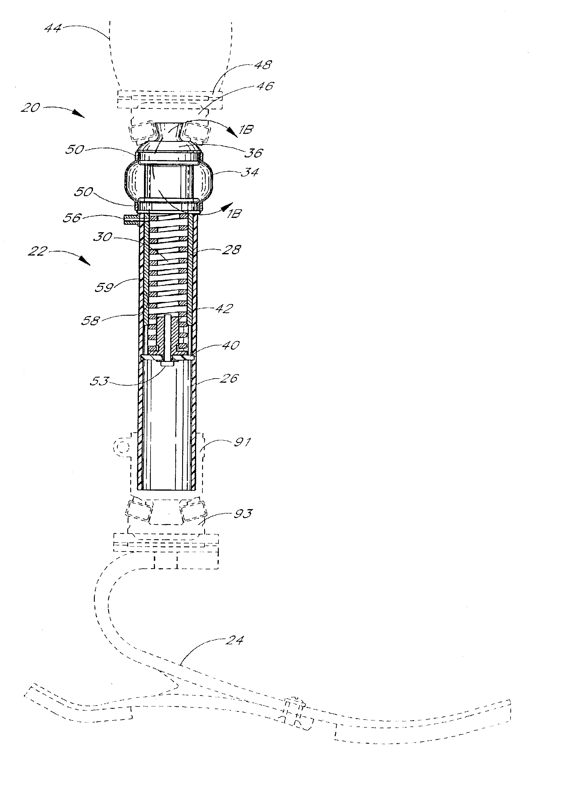
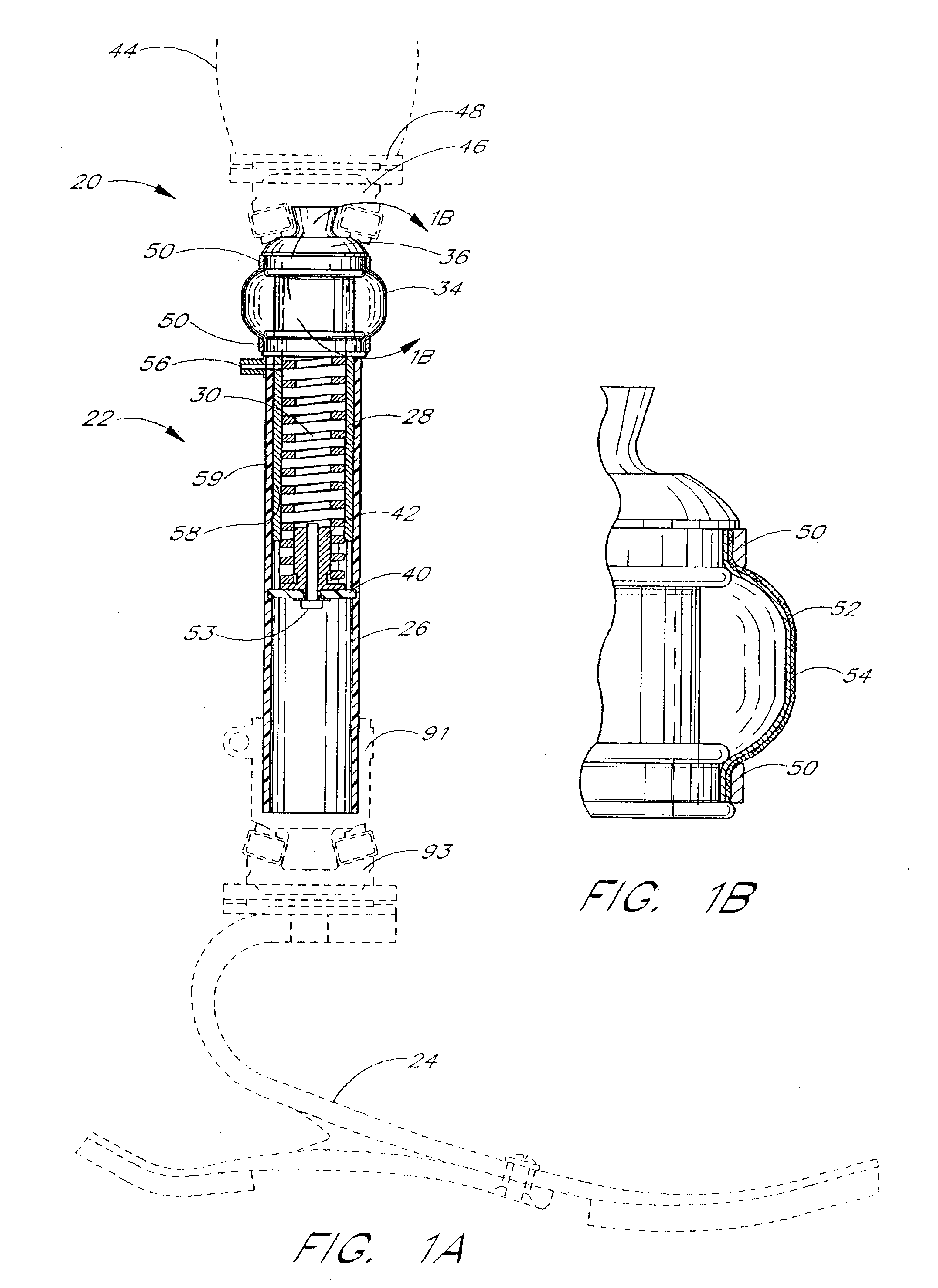
[0092]FIG. 1A shows a preferred embodiment of a lower limb prosthesis 20 including a shock module 22 constructed and assembled in accordance with the teachings of the present invention. For purposes of illustration, the prosthesis 20 is shown as also including a prosthetic foot 24, in this case a Flex-Walk® foot available from Flex-Foot, Inc. of Aliso Viejo, Calif., and a stump socket 44. In particular, the upper end of shock module 22 is connected to stump socket 44, illustrated by way of example by utilizing a female pyramid fitting 46 and an alignment cup 48.

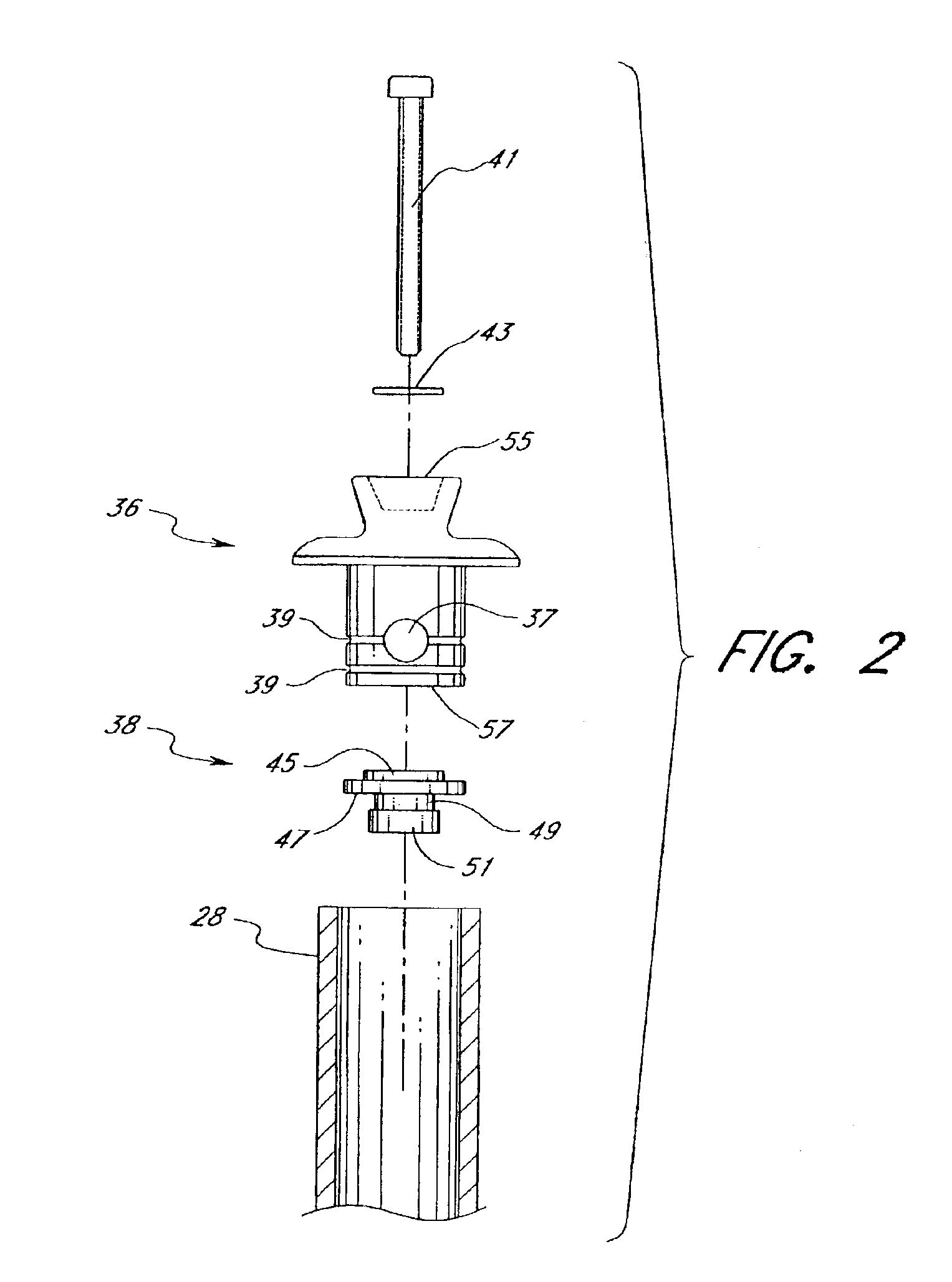
[0093]Shock module 22 includes telescoping hollow cylindrical pylons 26 and 28, shaped and adapted for smooth relative motion. Pylons 26 and 28 are preferably slidingly and rotationally interengaged with each other while retaining their operative horizontal alignment with each other through a relatively close fit between the inside dimensions of outer pylon 26 and the outside dimensions of inner pylon 28. Inner pylon 28 is ad...


PUM

PropertyMeasurementUnit
Lengthaaaaaaaaaa
Displacementaaaaaaaaaa
Electrical resistanceaaaaaaaaaa

Abstract

An impact-absorbing shock module comprises two pylons telescopingly engaged to permit axial and rotational motion therebetween. A resilient element, such as a spring-fluid combination, a plurality of interconnected disks, or a Belleville spring, provides axial shock absorption. A tubular torque-resisting cuff provides rotational resistance, or torsion-resistance. A fluid valve is optionally provided so that the fluid pressure may be varied to adjust the torsion resistance.

Description

RELATED APPLICATIONS[0001]This application is a continuation of application Ser. No. 09 / 556,249, filed on Apr. 24, 2000, now U.S. Pat. No. 6,511,512 which is a continuation-in-part of application Ser No. 09 / 289,533, filed on Apr. 9, 1999, now U.S. Pat. No. 6,478,826, which claims priority to provisional application Ser. No. 60 / 081,282, filed on Apr. 10, 1998. The entirety of each of these prior applications is hereby incorporated by reference.BACKGROUND OF THE INVENTION[0002]1. Field of the Invention[0003]The present invention relates to lower limb prostheses in general, and, in particular, to a shock module prosthesis having a spring and / or fluid resilient element for smooth impact absorption during use of the prosthesis, and also having an adjustable torque-resisting cuff permitting rotational compliance of the lower leg and foot.[0004]2. Description of the Related Art[0005]Various types of lower limb prostheses are known in the prior art. Such devices generally include some form ...

Claims


Application Information

Patent Timeline
IPC IPC(8): A61F2/60A61F2/00A61F2/66A61F2/50A61F2/76A61F2/74F16F1/04F16F1/14F16F1/32F16F1/36F16F1/40F16F1/48F16F15/04F16F15/10
CPCA61F2/60F16F15/10F16F1/042F16F1/32F16F1/3605F16F1/3615F16F1/40F16F1/48F16F15/04A61F2/76A61F2002/30235A61F2002/30276A61F2002/30507A61F2002/5003A61F2002/5006A61F2002/5032A61F2002/5033A61F2002/5073A61F2002/5084A61F2002/607A61F2002/6671A61F2002/74A61F2220/0025A61F2230/0069A61F2230/0086A61F2/6607A61F2/74
Inventor PHILLIPS, VAN L.POUCHAK, HILARY D.
Owner OSSUR HF
Why Eureka
Try Eureka