
Image forming method and image forming apparatus

a technology of image forming and forming apparatus, which is applied in the direction of electrographic process apparatus, instruments, printing, etc., can solve the problems of inability to carry out stable reversal development, inability to carry out stable development, and inability to form dots having uniform size and shap

Inactive Publication Date: 2005-05-03
KONICA CORP
View PDF1 Cites 0 Cited by
  • Summary
  • Abstract
  • Description
  • Claims
  • Application Information

AI Technical Summary

Benefits of technology

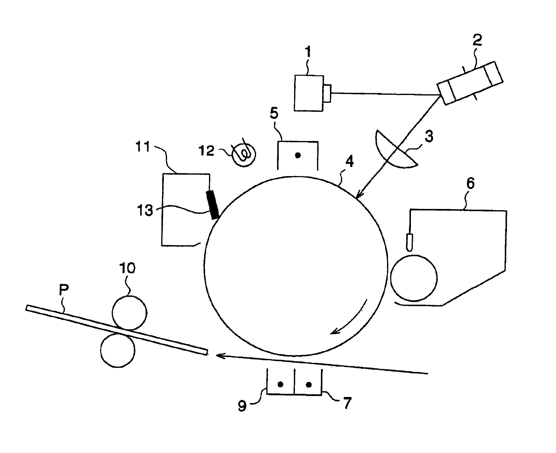
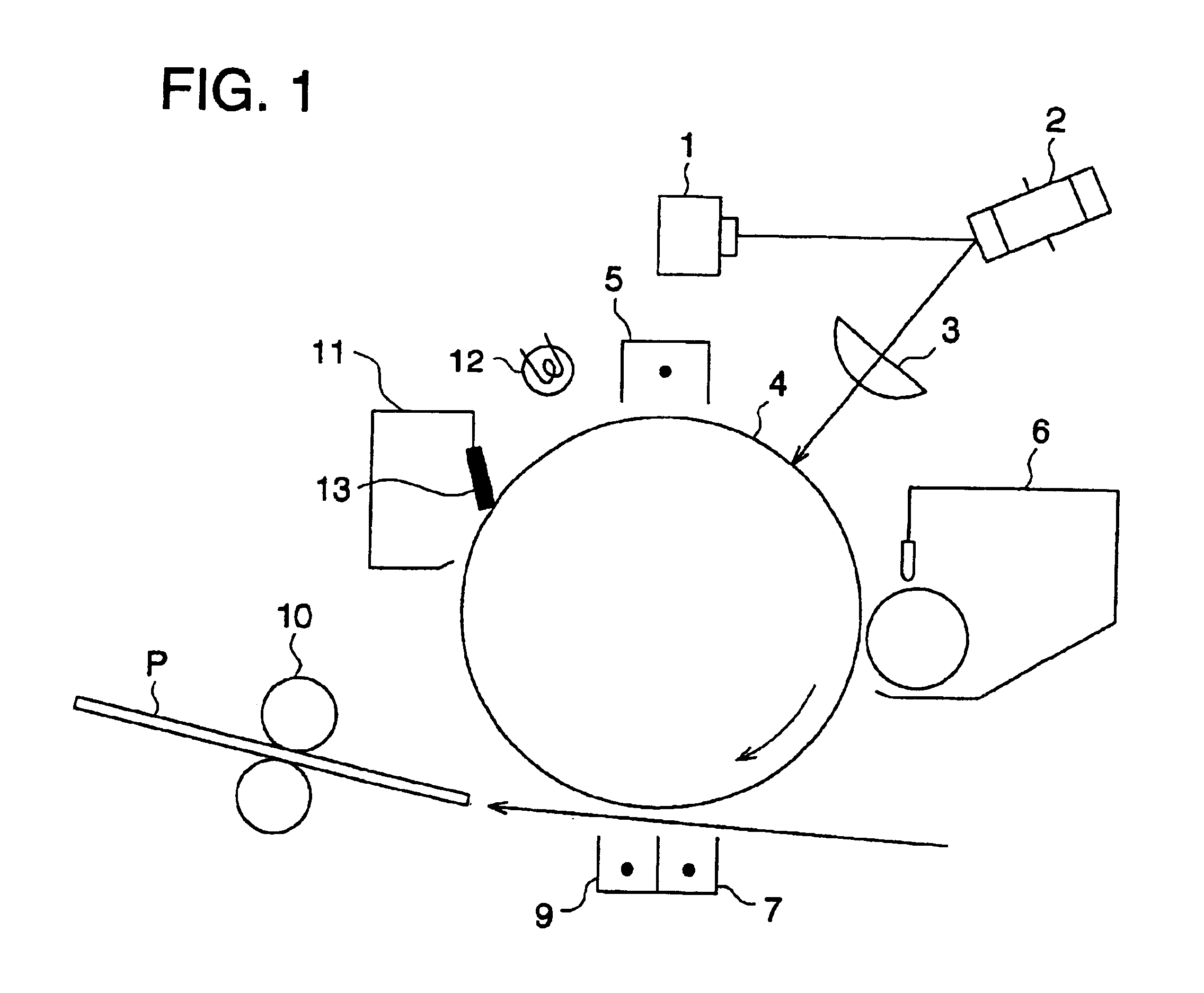
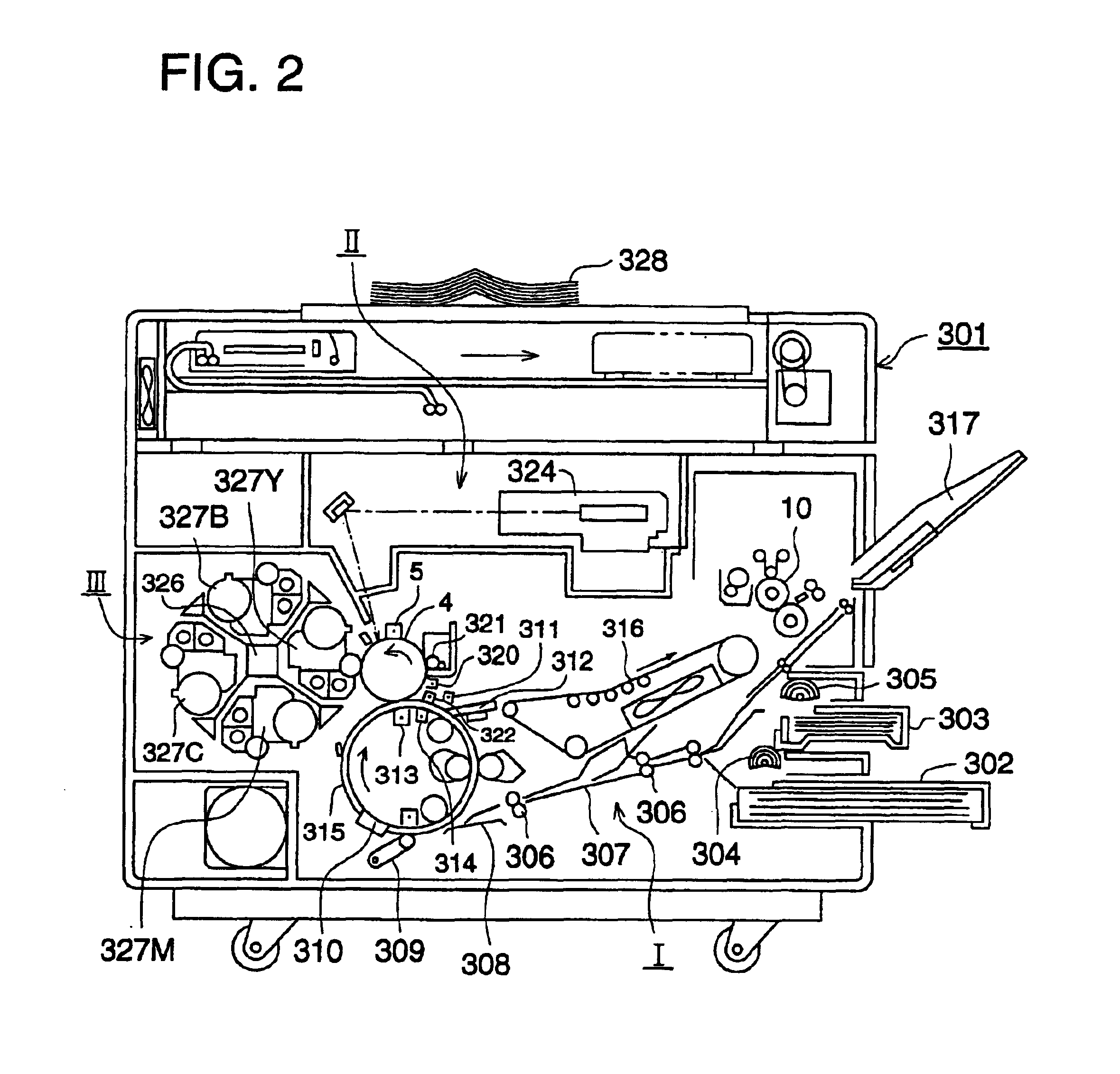
[0026]In recent years, in the field of electrophotography, and the like, in which an electrostatic latent image is formed on a photoreceptor, and in which the resulting latent image is developed to obtain a visualized image, research and development of an image forming method utilizing a digital system has been increasingly carried out in which improvement of image quality, conversion, editing, and the like, are easily performed, and the realization of high quality images is possible. Scanning optical systems, which carry out light modulation employing digital image signals from a computer used in said image forming method or apparatus, or from an original document for copying, include an apparatus which carries out light modulation employing an acoustic optical modulator, while providing said acoustic optical modulator into the laser optical system, an method in which LED is employed as the light source, and the like. From any of these scanning systems, spot exposure is carried out onto a uniformly charged photoreceptor and halftone images are formed.
[0031]By satisfying said relationship, it is possible to produce detailed images, to obtain reproducibility of fine lines, and further to produce so-called multiple generation copies at good quality.

Problems solved by technology

However, the reversal development is unstable as the development method, compared to the normal development, and as a result, it is difficult to carry out stable reversal development.
When a common toner is employed, it is impossible to carry out stable development with high reproducibility for electric potential having a semi-normal distribution when such a distribution exists at development.
Thus, it is impossible to form dots having uniform size as well as shape.

Method used


Image

  • Image forming method and image forming apparatus
  • Image forming method and image forming apparatus
  • Image forming method and image forming apparatus

Examples


production example 1

of Comparative Particles

[0169]A mixture consisting of 165 g of styrene, 35 g of n-butyl acrylate, 20 g of carbon black, 8 g of styrene-methacrylic acid copolymer, and 20 g of paraffin wax (having an mp of 70° C.) was heated to 60° C., and was dissolved and uniformly dispersed at 1,200 rpm employing a TK Homomixer (manufactured by Tokushukika Kogyo Co.). Added to the resulting dispersion was 10 g of 2,2′-azobis(2,4-valeronitrile) and was dissolved to prepare polymerizing monomer composition. Subsequently, 450 g of a 0.1 M aqueous sodium phosphate solution was added to 710 g of deionized water. While stirring the resulting solution at 12,000 rpm employing a TK Homomixer, 68 g of 1.0 M calcium chloride was gradually added to prepare a suspension in which tricalcium phosphate was dispersed.

[0170]Said polymerizing monomer composition was added to the resulting suspension. The resulting mixture was stirred at 13,000 rpm for 20 minutes employing a TK Homomixer, and the polymerizing monomer...

production example 2

of Comparative Particles

[0171]Colored particles were obtained by fusing, kneading, and pulverizing a mixture consisting of 100 parts of styrene acrylic resin, 10 parts of carbon black, and 4 parts of low molecular weight polypropylene (having a number average molecular weight of 3,000). The resulting particles were designated as “Comparative Particles 2”.

[0172]The shape coefficients, and the like of “Non-spherical Particles 1 through 5” and “Comparative Particles 1 and 2”, prepared as described above, are shown in Table 1 below.

[0173]

TABLE 1Volume% byNoAverageShapeNumberNo MoreMoreNon-sphericalParticleCo-betweenThanThanParticles No.Diameterefficient1.5 and 2.03.0 μm2.0 μmNon-spherical6.5 μm1.8692% by12%6%Particles 1numberNon-spherical6.2 μm1.6382% by18%8%Particles 2numberNon-spherical7.3 μm1.9392% by 6%2%Particles 3numberNon-spherical6.6 μm1.8692% by23%8%Particles 4numberNon-spherical6.5 μm1.8592% by25%17% Particles 5numberComparative6.4 μm1.1833% by36%18% Particles 1numberComparati...


PUM


Abstract

The image forming method carries out reverse development with a developer that has a toner prepared by agglomerating resin particles in a water based medium.

Description

[0001]This is a Divisional Application of U.S. patent application Ser. No. 10 / 052,418 filed Jan. 18, 2002, now U.S. Pat. No. 6,717,602 which, in turn, was a Continuation-in-part of U.S. patent application Ser. No. 09 / 604,584, filed Jun. 27, 2000, now abandoned.FIELD OF THE INVENTION[0002]The present invention relates to an image forming method as well as an image forming apparatus which carries out digital exposure, and an electrostatic latent image developing toner employed by the same.BACKGROUND OF THE INVENTION[0003]In recent years, high quality images have been increasingly demanded of image forming apparatuses such as copiers, printers, and the like which carry out digital exposure. Further, digital imaging has progressed in which electrostatic latent images are formed employing digital exposure and subsequently developed.[0004]In common images, the ratio of an area, to which a toner is practically applied to carry out printing, is no more than 30 percent with respect to the en...

Claims


Application Information

Patent Timeline
IPC IPC(8): G03G15/32G03G15/00G03G9/08
CPCG03G9/0804G03G9/0819G03G15/04045G03G15/326G03G9/0827G03G2215/0177
Inventor YAMAZAKI, HIROSHIYAMADA, HIROYUKISHIROSE, MEIZOKOUNO, SHIGENORI
Owner KONICA CORP
Learn More