
Data processing method, circuit, and apparatus with increased accuracy

a data processing and circuit technology, applied in the field of data processing methods, circuits, and apparatuses, can solve problems such as incorrect detection of data, waveform equalization reaches its limit, and multi-level data is wrongly determined

Inactive Publication Date: 2005-05-03
RICOH KK
View PDF28 Cites 15 Cited by
  • Summary
  • Abstract
  • Description
  • Claims
  • Application Information

AI Technical Summary

Benefits of technology

The present invention provides a data processing method, circuit, and apparatus for converting multi-level data to simpler and more accurate data. This is achieved by using a matrix of n-bit data, where each column contains a set number of bits of the data. The method involves arranging the data in a specific pattern and converting the data to m-bit data. This allows for more accurate reproduction of the original data. The invention also includes a method for determining the value of each symbol in the data based on ideal signal data values and a sum of errors between the data and the ideal values. Overall, the invention simplifies the process of converting multi-level data and improves the accuracy of the data.

Problems solved by technology

As recording density becomes higher, however, intersymbol interference increases, so that waveform equalization reaches its limit.
As a result, an excellent eye opening cannot be obtained, resulting in the problem of incorrect detection of data at the time of data reproduction.
However, if the data error occurs beyond the lower-side bits, the multi-level data is wrongly determined.
Therefore, when the multi-level data can take numerous values or a reproduction signal includes much noise, patterns in a table become less distinctive so that the multi-level data is likely to be determined wrongly.
This may cause an error at the time of outputting candidate multi-level data based on fixed thresholds, leading to the problem that the final reproduced multi-level data is wrongly determined.

Method used


Image

  • Data processing method, circuit, and apparatus with increased accuracy
  • Data processing method, circuit, and apparatus with increased accuracy
  • Data processing method, circuit, and apparatus with increased accuracy

Examples


first embodiment

[0080]Next, a description will be given of a data processing method according to the present invention.

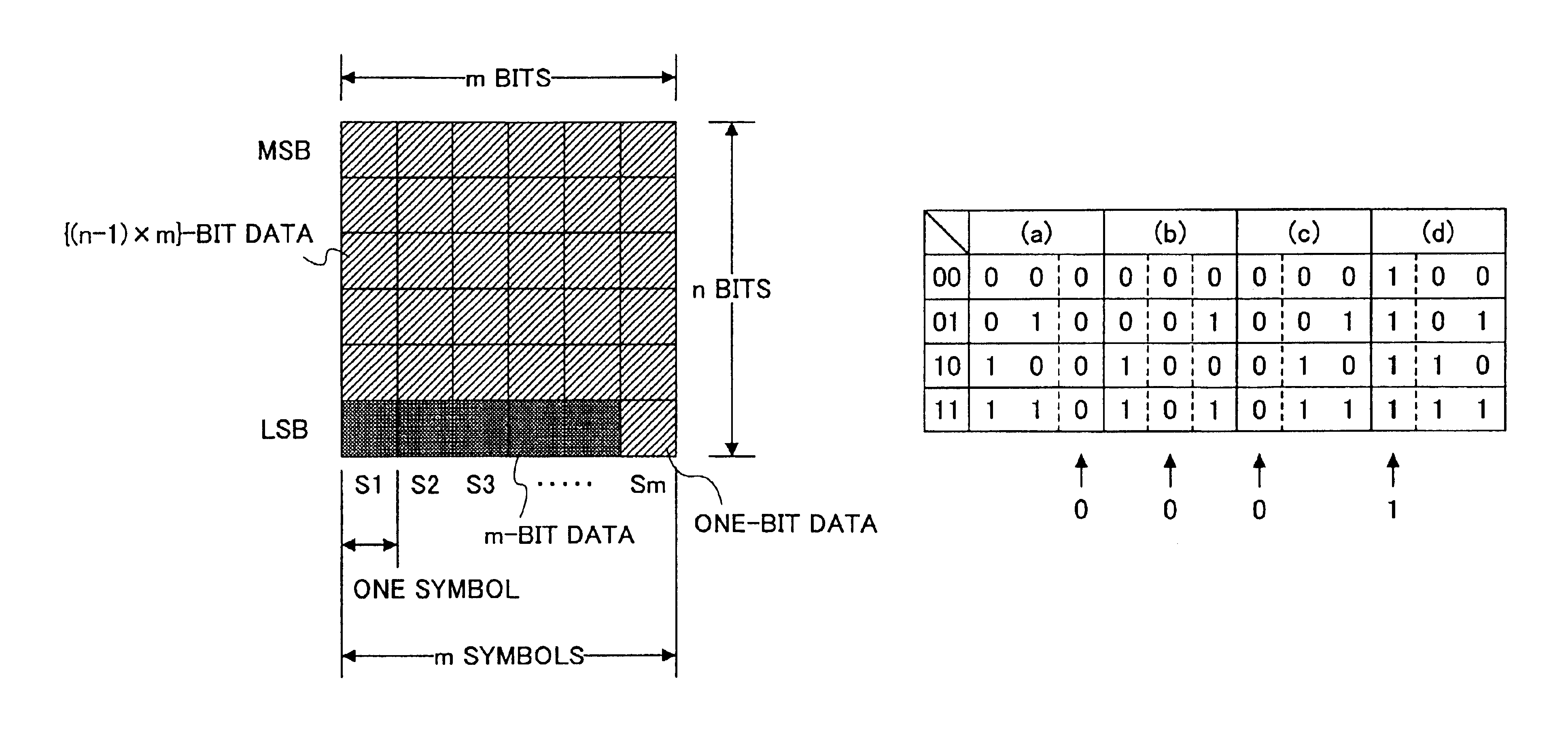
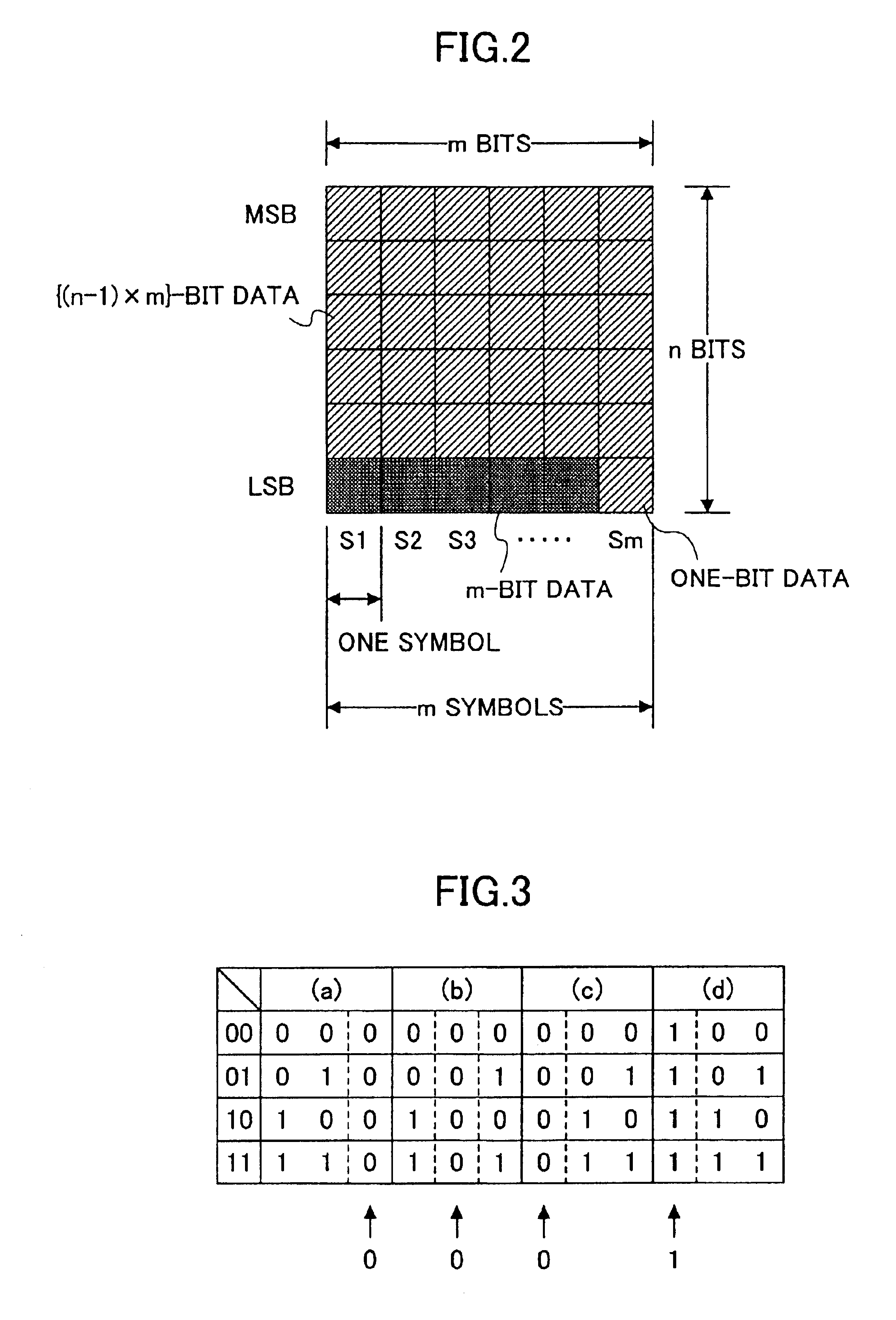
[0081]FIG. 2 is a diagram showing a matrix for illustrating the data processing method of the first embodiment.

[0082]Here, the multi-level data is treated as sets of a plurality of symbols (S1 through Sm) with each symbol being n-bit data (n is an integer satisfying n≧2) and each set consisting of m symbols (m is an integer satisfying m≧3).

[0083]In this case, each symbol can take 2n symbol values. MSB means the Most Significant Bit, and LSB means the Least Significant Bit.

[0084]A description will be given of a method of converting binary data to multi-level data.

[0085]First, {(n−1)×m}-bit binary data is arranged in the upper-side (n−1) bits of m symbols in one set.

[0086]Further, (m−1)-bit binary data is converted to m-bit binary data and arranged in the LSBs of the m symbols.

[0087]Thus, the (n×m−1)-bit binary data ({(n−1)×m}+(m−1)=(n×m−1)) is converted to the m symbols of multi-lev...

second embodiment

[0109]Next, a description will be given of a data processing method according to the present invention.

[0110]According to the data processing method of the second embodiment, the (m−1)-bit data is converted to the m-bit data by selecting and using one of two different conversion methods for each set instead of using only one conversion method for all the sets.

[0111]For instance, a numeric string P consisting of “0”s and “1”s arranged to correspond to the sets for selecting the conversion tables of (a) and (b), respectively, of FIG. 4 or 5 is defined as P=0, 1, 0, 1, 0, 1, . . . or P=0, 0, 1, 1, 0, 0, . . . . The conversion table may be determined with respect to each set so that the conversion table (a) is selected in the case of P=0 and the conversion table (b) is selected in the case of P=1. Further, random numbers defined by an initial value and a generation method may be used as the numeric string P.

[0112]Since all the m-bit patterns are thus employed, the data patterns of the s...

third embodiment

[0124]Next, a description will be given of a data processing method according to the present invention.

[0125]In the third embodiment, two-bit data is converted to multi-level data, and the multi-level signal is input as a signal reproduced from an information recording medium or received from a transmission path to be A / D-converted to digital data, from which the multi-level data is determined.

[0126]FIG. 6 is a diagram for illustrating the data processing method of the third embodiment.

[0127]Here, one symbol is two-bit multi-level data, and takes symbol values ranging from 0 to 3. Further, one set consists of four symbols.

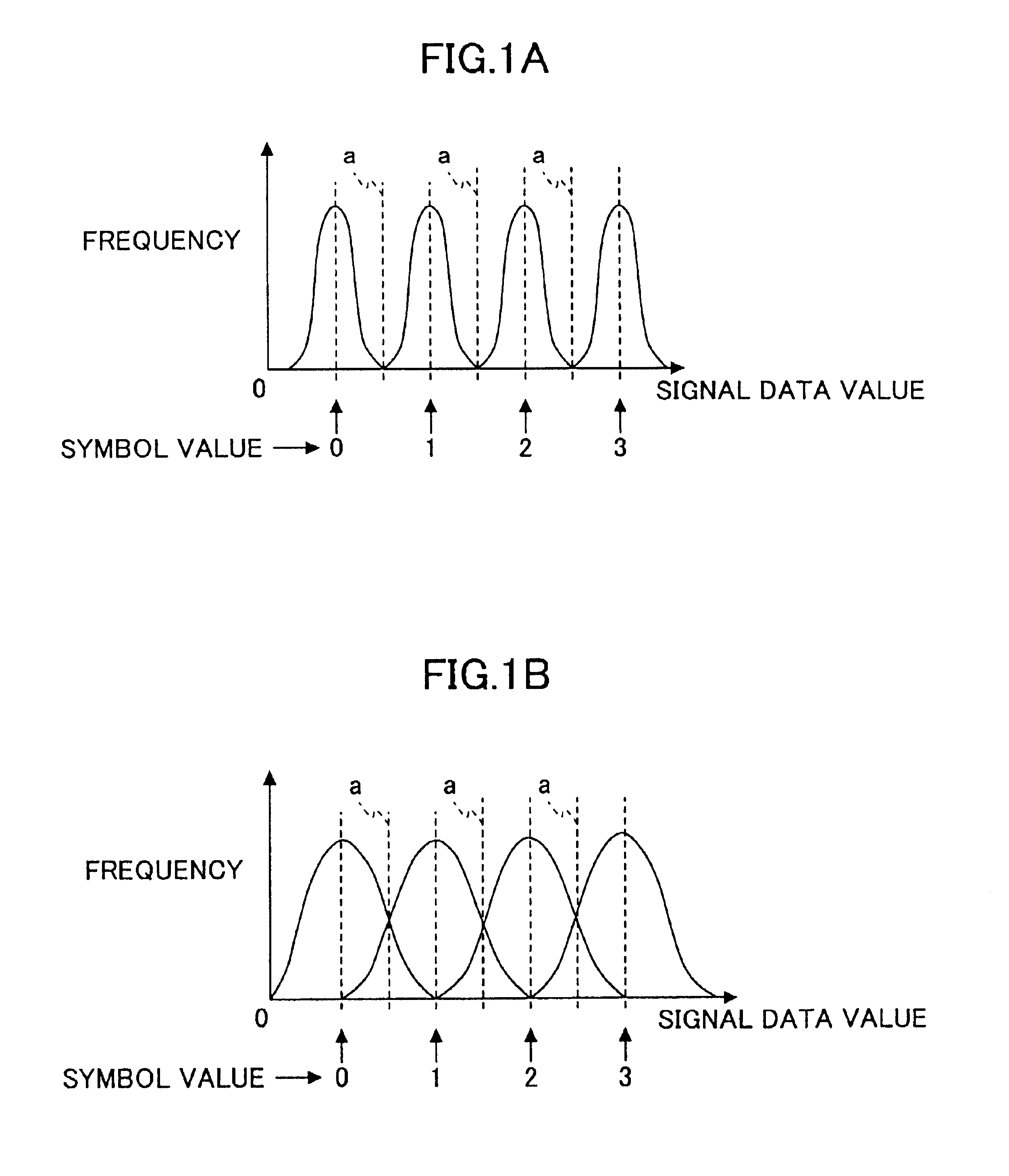
[0128]For simplification of description, the number of bits for quantization of A / D conversion is four, and signal data values range from decimal 0 to 15. Further, the symbol values “0”, “1”, “2”, and “3” correspond to ideal signal data values “2”, “6”, “10”, and “14”, respectively.

[0129]FIG. 7 is a table showing the relationship between the signal data value of an...


PUM

PropertyMeasurementUnit
timeaaaaaaaaaa
recording densityaaaaaaaaaa
lengthsaaaaaaaaaa

Abstract

In a data processing method of converting (n×m−1)-bit data to multi-level data of m symbols of n bits per symbol, n and m being integers satisfying n≧2 and m≧2, respectively, the m symbols each comprising n-bit data are arranged in m columns in an n×m matrix, with a value of each of the m symbols being set to an even or odd number, by creating the m symbols each including (n−1)-bit data of the (n×m−1)-bit data, arranging the m symbols in the m columns so that the {(n−1)×m}-bit data is arranged in upper-side {(n−1)×m} bits of the n×m matrix, and converting the remaining (m−1)-bit data of the (n×m−1)-bit data to m-bit data so that the m-bit data is arranged in a row in lower-side m bits of the n×m matrix.

Description

BACKGROUND OF THE INVENTION[0001]1. Field of the Invention[0002]The present invention generally relates to data processing methods, circuits, and apparatuses, and more particularly to a data processing method that is useful in recording a multi-level signal on and reproducing a multi-level signal from an information recording medium such as an optical disk (for instance, a CD-R disk, a CD-RW disk, or a DVD disk), a magneto-optical disk, a magnetic disk, or a magnetic tape, or in transmitting and receiving a multi-level signal through a wireless or wire transmission path, a data processing circuit mounted in an information storage device or a communication device to which the data processing method is applied, and a data processing apparatus, such as an information storage device or a communication device, to which the data processing method is applied.[0003]2. Description of the Related Art[0004]Japanese Laid-Open Patent Application No. 8-124167 discloses an optical information reco...

Claims


Application Information

Patent Timeline
Patent Type & Authority Patents(United States)
IPC IPC(8): G11B20/14H03M5/00H03M5/14
CPCH03M5/145G11B20/1426
Inventor SAKAGAMI, KOUBUNTAKATSU, KAZUNORISHIMIZU, AKIHIKOKADOKAWA, YUICHI
Owner RICOH KK
Learn More