Method and apparatus for economical drift compensation in high resolution measurements

a high-resolution measurement and drift compensation technology, applied in the field of measuring and recording devices, can solve the problems of significant limiting factors, amplitude and temperature component drift is typically much greater than the amplitude, and the active and passive electronic components of such systems are subject to time and temperature drift, and achieve accurate measurement of small signals and signal differences. , the effect of low cos

Inactive Publication Date: 2005-05-03
MORE EDWARD S
View PDF1 Cites 28 Cited by
  • Summary
  • Abstract
  • Description
  • Claims
  • Application Information

AI Technical Summary

Benefits of technology

[0013]It is therefore a general object of the present invention to provide a very low cost means of accurately measuring small signals and signal differences.

Problems solved by technology

It is known in the art that active and passive electronic components in such systems are subject to time and temperature drift, and that under normal operating conditions, the amplitude of time and temperature component drift is typically much greater than the amplitude of other inaccuracies generated by system components, such as amplifier noise voltage, noise current, and resistor noise.
Consequently, component time and temperature drift are significant limiting factors to high resolution measurements, such as temperature difference measurements.
While such hardware compensation systems provide some compensation for thermal drift inaccuracies, they do not compensate for component drift over time, particularly the drift of sensors, such as thermistors.
Additionally, such hardware based compensation techniques do not readily compensate for component drift, resulting from the combined time drift characteristics of multiple system components, located at different parts of the system, with different thermal drift characteristics, and subject to non-uniform aging.
In any case, the ability of the above hardware based compensation systems and techniques to compensate for system thermal drift are limited by the extent to which the particular technique tracks with thermal drift of the overall system, over time and temperature.
Consequently, such techniques would not provide sufficient compensation for component time and temperature drift to permit differential temperature measurements, with resolution on the order of micro-degrees centigrade, if these techniques were applied to that purpose.
The required precision analog components in these systems results in increased cost, complexity, and power consumption.
Moreover, these systems do not compensate for time drift of passive components, such as thermistors, which would be sufficient to preclude temperature difference measurements, with resolution on the order of micro-degrees centigrade, if these systems were applied to that purpose.
The prior art measurement systems, which utilize a computer, can provide time and temperature compensation based only upon the most recent reference calibration data, the acquisition of which requires that the system be cycled through an entire temperature range, and is sufficiently time consuming to prevent, or significantly interrupt, normal system operation.
), as well as in U.S. Pat. No. 4,464,725 (Briefer, referred to above), require the use of a time and temperature stable reference signal, which increases cost, complexity, and power consumption.
U.S. Pat. No. 4,959,804 (Willing) utilizes time and temperature stable passive components, which, even with costly bulk metal foil, or wirewound, resistors, would not provide the accuracy necessary in temperature difference measurements, with resolution on the order of micro-degrees centigrade, if this technique were applied to that purpose.
Such time and temperature stable bulk metal foil resistors (e.g., manufactured by Vishay Electronics Foil Resistors, of Malvern, Pa.) and wirewound resistors, such as manufactured by Dale Electronics, of Norfolk, Nebr., are one to two orders of magnitude more expensive than standard metal film resistors, which provide comparable time stability, but are not nearly as temperature stable.
U.S. Pat. No. 4,651,292 (Jeenicke) relies on updating a point on a measurement curve, requiring, however, the restriction that the sensor curve characteristic be linear (not the case with temperature sensors, such as thermistors, and not sufficiently so, to provide resolution on the order of micro-degrees centigrade, even with known thermistor linearization techniques) and that ambient temperature measurements not drift with time, to the extent that measurement accuracy would be affected, making this technique unsuitable for a differential thermometer with resolution on the order of micro-degrees centigrade, if such a technique were to be applied to that purpose.
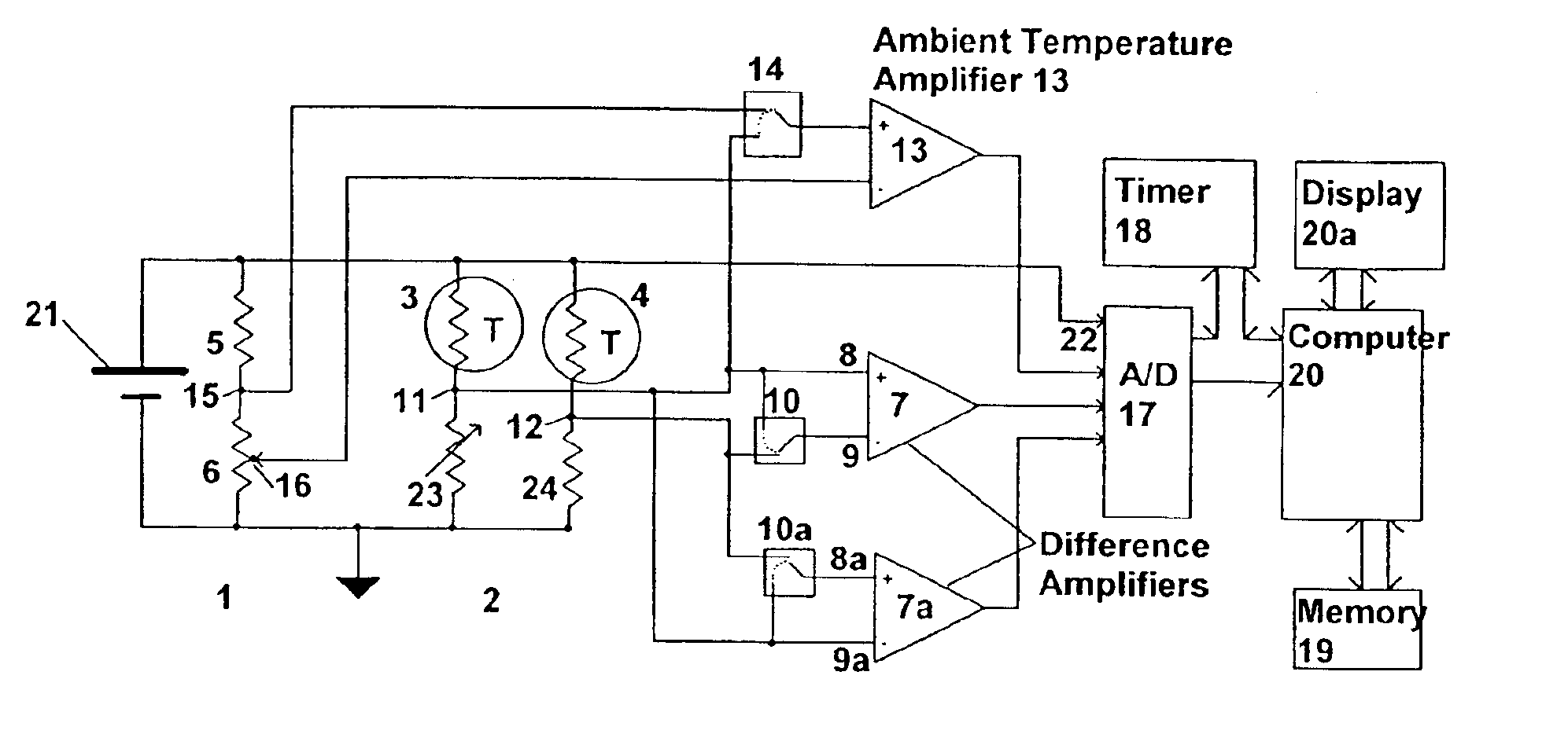
The above approaches, as they would relate to a temperature difference measurement system, utilizing a pair of thermistors, do not provide a means to compensate for this effect.
Additionally, in order to minimize common mode amplifier error, the use of bipolar power to the measurement bridge is often preferred in the above prior art, as are high precision amplifiers, which typically require bipolar power, resulting in added cost and complexity, compared to a single-ended power supply architecture.
However, this requires that the bridge circuit be balanced with extreme accuracy, requiring the addition of two digital to analog converters to the circuit, preferably employing high resolution, in order to achieve high resolution temperature difference measurements, resulting in added component count, cost, and power consumption.
Additionally, no means is provided to compensate for time drift of thermistors, which typically amounts to ten or more milli-degrees / year (e.g., YSI 44018, manufactured by YSI Incorporated, of Yellow Springs, Ohio), a significant figure in temperature difference measurements, intended to approach micro-degree centigrade resolution.
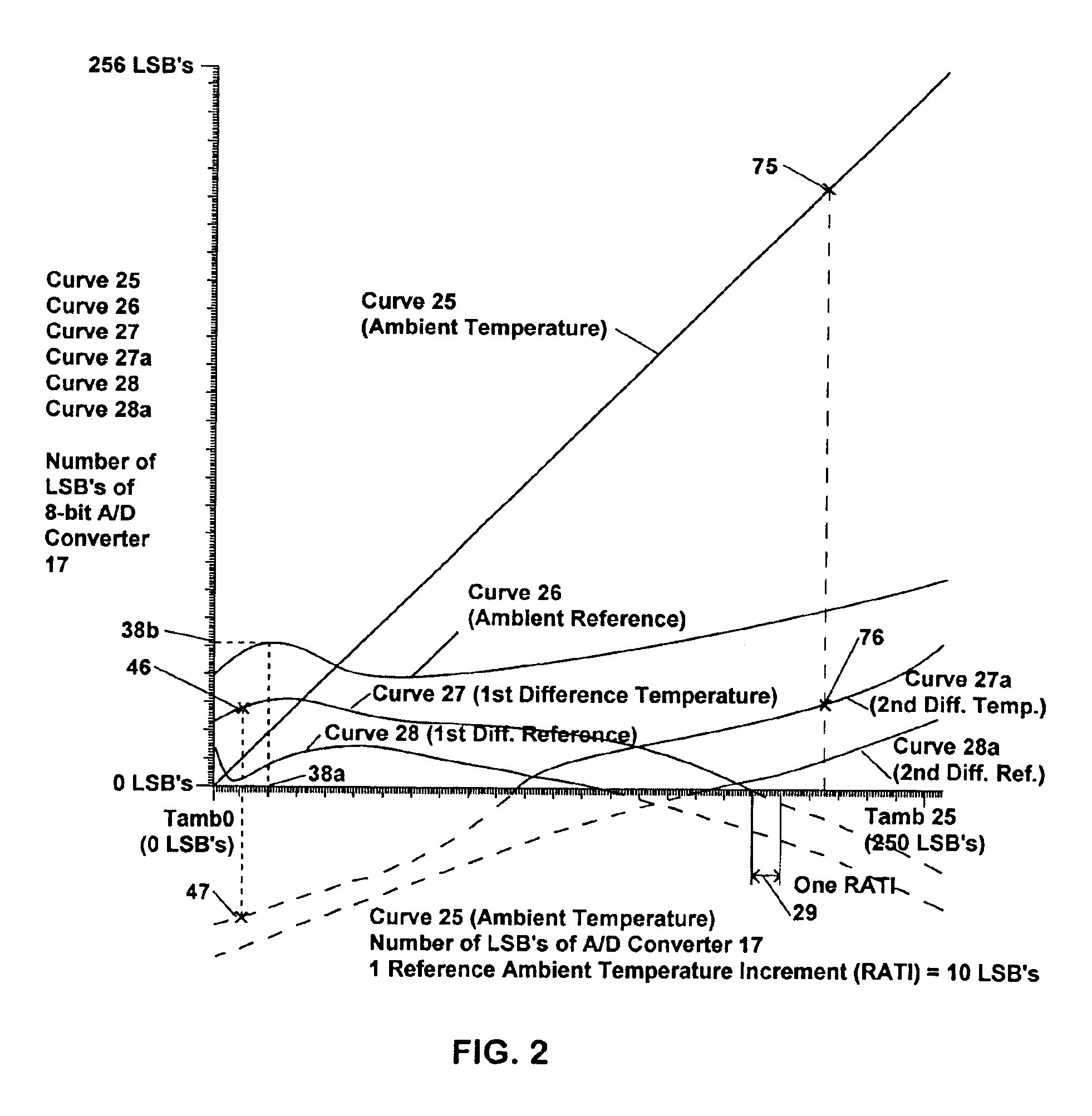
In cases where temperature difference measurements on the order of micro-degrees centigrade are to be resolved, this powering down and then powering up of the bridge, until the thermistors are within micro-degrees centigrade of equilibrium, adds significant time to the calibration process.
Calibration measurements performed before and after a measurement run can conceivably be used to interpolate linear changes in ambient temperature with time, during a measurement run, but this places an unrealistic limitation on a measurement system which desirably operates under normal atmospheric conditions, in which ambient temperature changes may not be linear with time.
Therefore, a calibration measurement must be undertaken for each temperature difference measurement, in which ambient temperature may not have undergone a linear change, thus adding significant time to the measurement process.
Similarly, U.S. Pat. No. 5,351,010 (Leopold et al., also mentioned above) requires that current be reversed through zero, in resistive sensors, for each calibration, as well as requiring precision circuitry, that increases cost, complexity, and power consumption.
Additionally, the prior art does not provide a means to dynamically quantify compensation inaccuracies, resulting from the particular drift compensation technique used.
An additional source of error to take into consideration, in devices expected to perform to specification when they are turned on, includes time versus drift behavior during system warm-up.

Method used


Image

  • Method and apparatus for economical drift compensation in high resolution measurements
  • Method and apparatus for economical drift compensation in high resolution measurements
  • Method and apparatus for economical drift compensation in high resolution measurements

Examples


Embodiment Construction

[0048]Referring to FIG. 1, one exemplary embodiment of the present invention, providing a low cost, high resolution digital temperature difference thermometer, includes: a reference bridge 1; a measurement bridge 2; a first thermistor 3 and a second thermistor 4, said thermistors configured in parallel, as shown at the upper half of measurement bridge 2; reference resistors 5 and 6, comprising reference bridge 1, arranged as shown, between power rails of measurement bridge 2; a first high gain difference temperature amplifier 7, with inputs 8 and 9, which can be connected via a switch 10 to measurement nodes 11 and 12, respectively, of measurement bridge 2, or shorted together such that inputs 8 and 9 are both connected to bridge node 11; a second high gain difference temperature amplifier 7a, with inputs 8a and 9a, which can be connected via a switch 10a to measurement nodes 12 and 11, respectively, of measurement bridge 2, or shorted together such that inputs 8a and 9a are both co...


PUM

PropertyMeasurementUnit
temperatureaaaaaaaaaa
operating temperaturesaaaaaaaaaa

Abstract

A system for measuring differences in a physical variable, such as temperature or voltage, by utilizing predictable behavior in the relative drift over time of reference curves representative of offset, and other measurement parameters for various circuit elements. In an initial calibration mode, the system records several reference curves, correlating ambient condition to offset, and, optionally, other parameter measurements acquired from circuit elements. These reference curves representing drift behavior, among electrical components, can be updated for time drift at a single, current arbitrary ambient temperature, the measurements for which can be obtained quickly and applied as a time drift correction to the reference curves, without interrupting normal system operation, to provide a compensated difference measurement between the different values of the physical variable. Additionally, the system dynamically tracks cumulative system errors, in order to calculate optimal system resolution, based upon current operating conditions.

Description

CROSS-REFERENCES TO RELATED PATENT APPLICATIONS[0001]This is a continuation-in-part of U.S. patent application Ser. No. 10 / 029,898, filed on Dec. 21, 2001, now U.S. Pat. No. 6,651,020, entitled “METHOD AND APPARATUS FOR ECONOMICAL DRIFT COMPENSATION IN HIGH RESOLUTION MEASUREMENTS,” which is a continuation-in-part of U.S. patent application Ser. No. 09 / 273,094 filed on Mar. 19, 1999, now U.S. Pat. No. 6,334,093, which is a continuation-in-part of abandoned U.S. patent application Ser. No. 08 / 997,901, filed on Dec. 24, 1997, now abandoned, both entitled “METHOD AND APPARATUS FOR ECONOMICAL DRIFT COMPENSATION IN HIGH RESOLUTION DIFFERENCE MEASUREMENTS AND EXEMPLARY LOW COST, HIGH RESOLUTION DIFFERENTIAL DIGITAL THERMOMETER.”TECHNICAL FIELD[0002]The present invention relates to measuring and recording devices and techniques for compensating electronic measurement systems for the effects of electronic component drift over time and temperature. By way of example but without limitation, o...

Claims


Application Information

Patent Timeline
Patent Type & Authority Patents(United States)
IPC IPC(8): G01K3/14G01K3/00H03M1/10
CPCH03M1/1038G01K3/14
Inventor MORE, EDWARD S.
Owner MORE EDWARD S
Why Eureka
Try Eureka