Four wheel-drive vehicle

a four-wheel drive, vehicle technology, applied in the direction of trailer steering, fluid gearing, gearing, etc., can solve the problems of unable to use the power take-off shaft for driving the working device as a front-wheel drive shaft simply, lack of stability when working on slopes and road abilities, and difficulty in bailing out vehicles buried in mud or the like, etc., to achieve high flexibility of parts arrangement and save costs

Inactive Publication Date: 2005-05-10
KANZAKI KOKYUKOKI MFG
View PDF13 Cites 43 Cited by
  • Summary
  • Abstract
  • Description
  • Claims
  • Application Information

AI Technical Summary

Benefits of technology

[0013]A first object of the present invention is to provide a four-wheel drive vehicle with high flexibility of parts arrangement dep

Problems solved by technology

The two-wheel-drive vehicle driving only rear wheels is advantageous in steering performance, however, it lacks stability when working on a slope and road ability when running on a bad road.
Moreover, the vehicle mired in mud or the like is difficult to bail out.
Thus, the power take-off shaft for driving the working device cannot be used as a front-wheel drive shaft simply.
Even if another power take-off shaft is allowed to be provided in the transaxle apparatus on the rear frame so as to take out output power of the HST and to drive the front wheels synchronously to the r

Method used


Image

  • Four wheel-drive vehicle
  • Four wheel-drive vehicle
  • Four wheel-drive vehicle

Examples


first embodiment

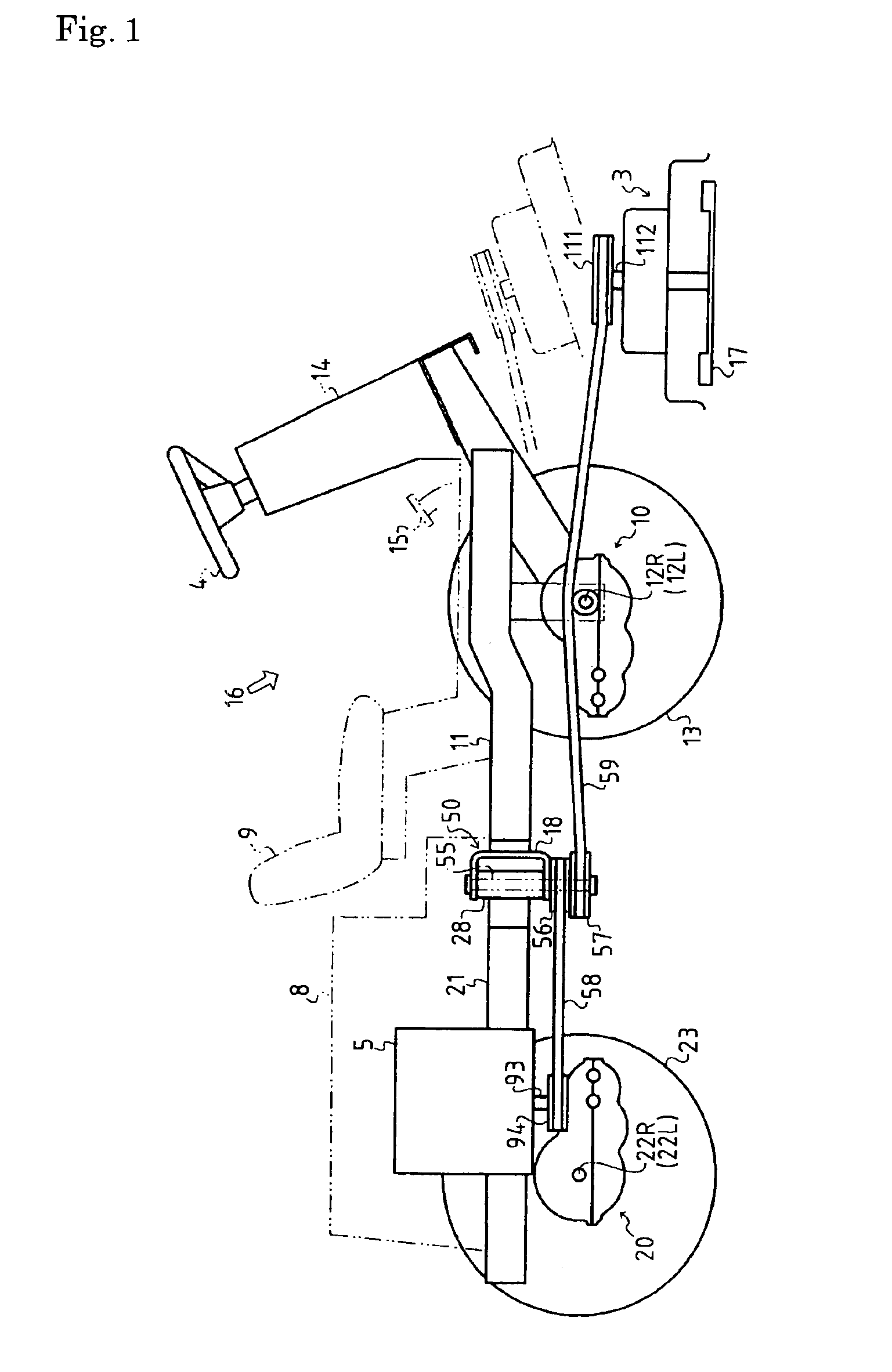
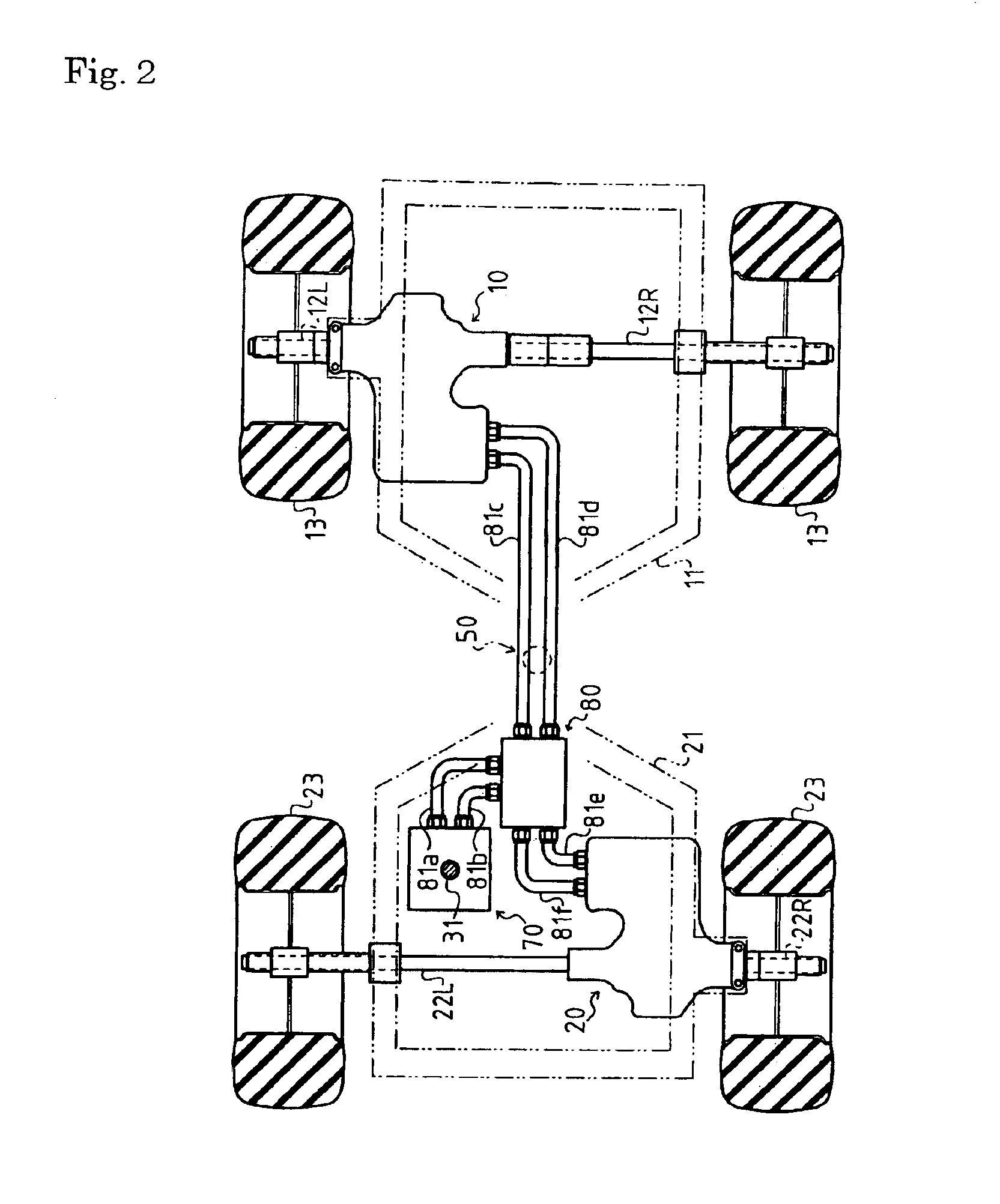
[0061]To begin with, description will be given of a structure of a riding lawn mower according to the present invention shown in FIGS. 1 to 9. FIG. 1 shows the riding lawn mower equipped at a front portion thereof with a mower device 3 serving as a working device. A front transaxle apparatus 10 is arranged on a front frame 11, and front wheels 13 are fixed to respective front wheel axles 12L and 12R extended laterally from the front transaxle apparatus 10. On the other hand, a rear transaxle apparatus 20 is arranged to a rear frame 21, and rear wheels 23 are fixed to respective rear wheel axles 22L and 22R extended laterally from the rear transaxle apparatus 20.

[0062]At a pivotal coupling part 50, a rear end part of the front frame 11 and a front end of the rear frame 12 are horizontally rotatably coupled to each other so that the rear frame 21 can be laterally folded relative to the front frame 11, thereby constituting an articulate vehicle serving as the riding lawn mower.

[0063]An...

second embodiment

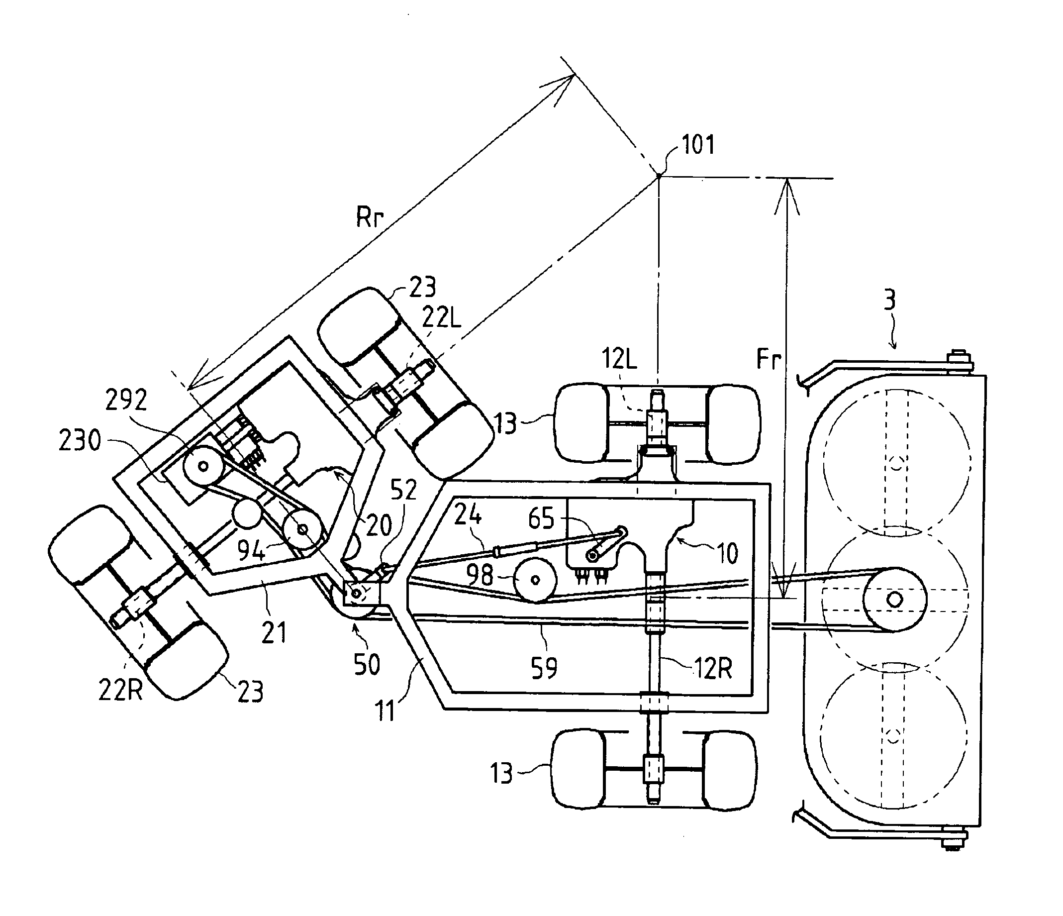
[0134]Next, description will be given of a four-wheel-drive articulate working vehicle according to the present invention shown in FIGS. 12 to 22. FIGS. 12 and 13 show a working vehicle equipped at a front portion thereof with a mower device 3 serving as a working device. This vehicle has a front frame 11, which is longer than a rear frame 21 pivotally connected to the front frame 11. The front frame 11 is provided with a front transaxle apparatus 10 from which front wheel axles 12L and 12R (hereinafter, “a front wheel axle 12” is used as a generic name of the front wheel axles 12L and 12R) are extended in a transverse direction and fixed to respective front wheels 13. The rear frame 21 is provided with a rear transaxle apparatus 20 from which rear wheel axles 22L and 22R (hereinafter, “a rear wheel axle 22” is used as a generic name of the rear wheel axles 22L and 22R) are extended in a transverse direction and fixed to respected rear wheels 23.

[0135]A rear end portion of the front...

third embodiment

[0201]In the third embodiment, as shown in FIGS. 23 and 24, the coupling part 50 is provided with a stay 52a fixed to the pivotal connector 18 on the front frame 11 side, a link rod 24a is extended backward from a tip of the stay 52a, and connected to the motor control lever 65 of the rear transaxle apparatus 200, thereby being connected the movable swash plate 44 of the variable displacement hydraulic motor 40 in the rear transaxle apparatus 200. Namely, corresponding to the bending angle of the vehicle body, the rod 24a is moved so as to steplessly change the tilt angle of the movable swash plate 44 of the variable displacement hydraulic motor 40 in the rear transaxle apparatus 200, thereby changing the relative velocity between the front wheel axle 12 (axles 12L and 12R) and the rear wheel axle 22 (axles 22L and 22R).

[0202]However, in the third embodiment, since the variable displacement transaxle apparatus 40 is provided in the rear transaxle apparatus 200 on the rear frame 21 w...


PUM


Abstract

An articulate vehicle comprises a first frame disposed at one of front and rear portions of the vehicle and a second frame disposed at the other of front and rear portions of the vehicle. The first frame supports a first transaxle apparatus supporting a first axle. The second frame supports a second transaxle apparatus supporting a second axle. Proximal ends of the frames with respect to the vehicle are coupled to each other through a coupling part so that the first and second frames are rotatable relative to each other around a vertical axis according to steering operation. An engine is mounted on the first frame. A first hydraulic motor is integrally assembled in the first transaxle apparatus so as to drive the first axle. A working vehicle is equipped at a distal side of the second frame with respect to the vehicle. A second hydraulic motor is integrally assembled in the second transaxle apparatus so as to drive the second axle. A hydraulic pump is mounted on either the first or second frame, drivingly connected to the engine, and fluidly connected to both the first and second hydraulic motors.

Description

BACKGROUND OF THE INVENTION[0001]1. Field of the Invention[0002]The invention relates to a four-wheel-drive vehicle, particularly to a four-wheel drive articulate working vehicle such as a riding lawn mower. More particularly, it relates to a structure of a transaxle apparatus in the vehicle, and a structure for drivingly connecting front and rear transaxle apparatuses in the vehicle to each other.[0003]2. Related Art[0004]Conventionally, there is a well-known articulate riding lawn mower with pivotally connected first and second frames so as to allow the second frame to be folded relative to the first frame around a vertical axial pivot by steering operation (i.e., manipulation of a steering wheel). The first frame is equipped with an engine and a transaxle apparatus supporting a first axle driven by the engine. The second frame is equipped with a working device such as a mover device, a driver's unit, and an axle casing supporting a freely rotatable second axle. Furthermore, a rid...

Claims


Application Information

Patent Timeline
IPC IPC(8): A01D34/63A01D69/00A01D69/03B60K7/00B60K17/10B60K17/356B60K17/34F16H39/00F16H7/02F16H39/14B60K17/00B62D12/00F16H37/08F16H59/58F16H61/456
CPCA01D34/63A01D69/03B60K17/105B60K17/356B60K17/358F16H61/456B62D12/00F16H61/423F16H61/444A01D2101/00F16H7/02F16H39/14F16H59/58B60Y2200/223
Inventor OKADA, HIDEAKITSUKAMOTO, MICHIOABEND, ROBERT
Owner KANZAKI KOKYUKOKI MFG
Why Eureka
Try Eureka