Method and apparatus for vein fluid removal in heart failure

a vein and fluid extraction technology, applied in the field of congestive heart failure treatment methods and equipment, can solve the problems that the device requiring central access to venous blood was generally not used, and achieve the effects of reducing chf symptoms, simple excess fluid extraction (safe), and widespread clinical us

Inactive Publication Date: 2005-05-10
GAMBRO LUNDIA AB
View PDF35 Cites 129 Cited by
  • Summary
  • Abstract
  • Description
  • Claims
  • Application Information

AI Technical Summary

Benefits of technology

[0061]One advantage of the invention is that it does not require surgery or ICU, and can be administered to patients in emergency rooms, clinics and other such facilities. The majority of the total of the 2.5 million CHF patients admitted per year in the United States do not require an ICU. The admission of many of these cases to the hospital could be adverted altogether if there existed a safe, simple means to remove excess fluid from these patient to relieve the CHF symptoms of fluid overload.
[0062]The invention includes a device that is suited to extract excess fluid from a CHF patient at a clinically relevant rate that will overcome the deficiencies of existing machines for renal replacement therapy and particularly could be used outside of an ICU. The invention provides a simple excess fluid extraction (SAFE) system for use with CHF patients.
[0063]The invention avoids the need for a central access to venous blood. Central access catheters such as 10 or 14FR catheters from Medcomp PA can are primarily used in the ICU or special dialysis setting. Thus, a device requiring central access to venous blood was generally not used to treat CHF patients, other than the most sick CHF patients.
[0064]The invention provides an acceptable level of invasiveness for a fluid removal treatment in the desired environment and patient population via a peripheral vein preferably in an arm of a patient. Such access is commonly established by a nurse to draw blood or to infuse drugs. The invention does not require an ICU or a special dialysis setting to be administered to a patient. If an apparatus for slow continu

Problems solved by technology

Thus, a device requiring central access to venous blood was generally

Method used


Image

  • Method and apparatus for vein fluid removal in heart failure
  • Method and apparatus for vein fluid removal in heart failure
  • Method and apparatus for vein fluid removal in heart failure

Examples


Embodiment Construction

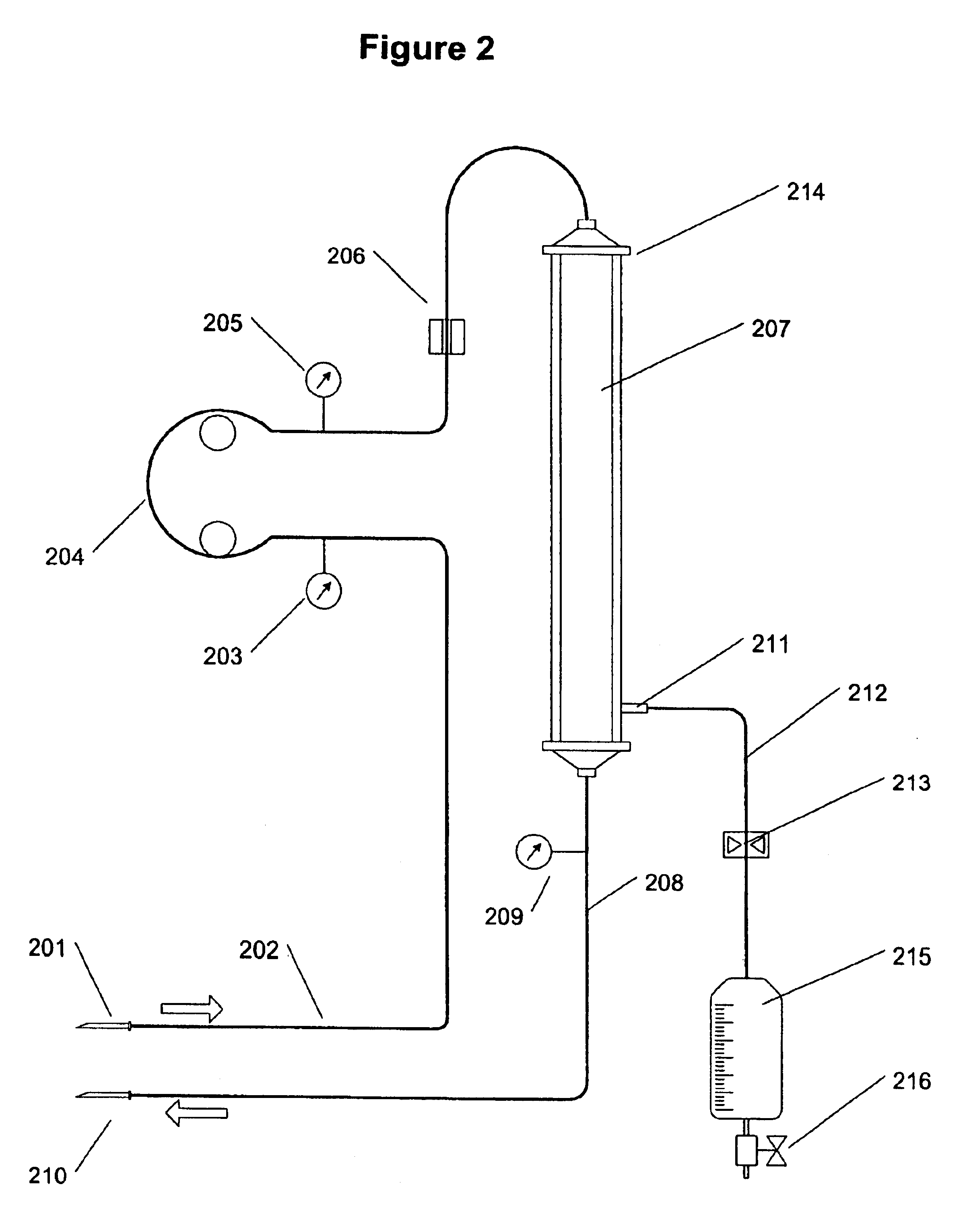
[0085]For the proposed clinical use, the capability of the invention is to remove water drove the design. This is fortunate since the convection technique proposed here for removal of water is inefficient (in terms of the solute material removed per unit of the surface area of the membrane) in removing solute from the blood plasma. The functional kidneys of the patient are relied on to remove solutes from the plasma. The kidneys are, thus, relived of having to perform substantially all fluid removal from the blood.

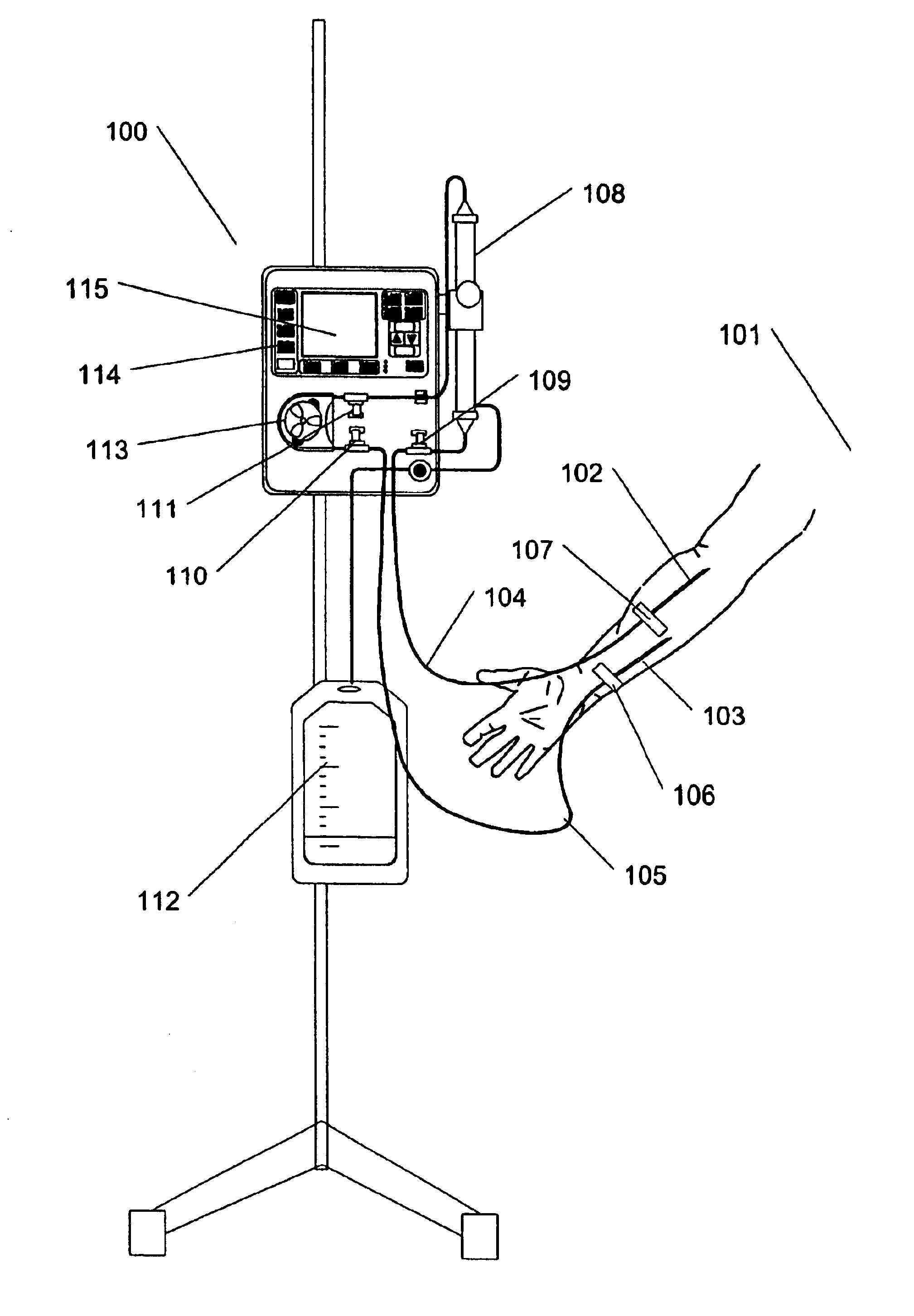
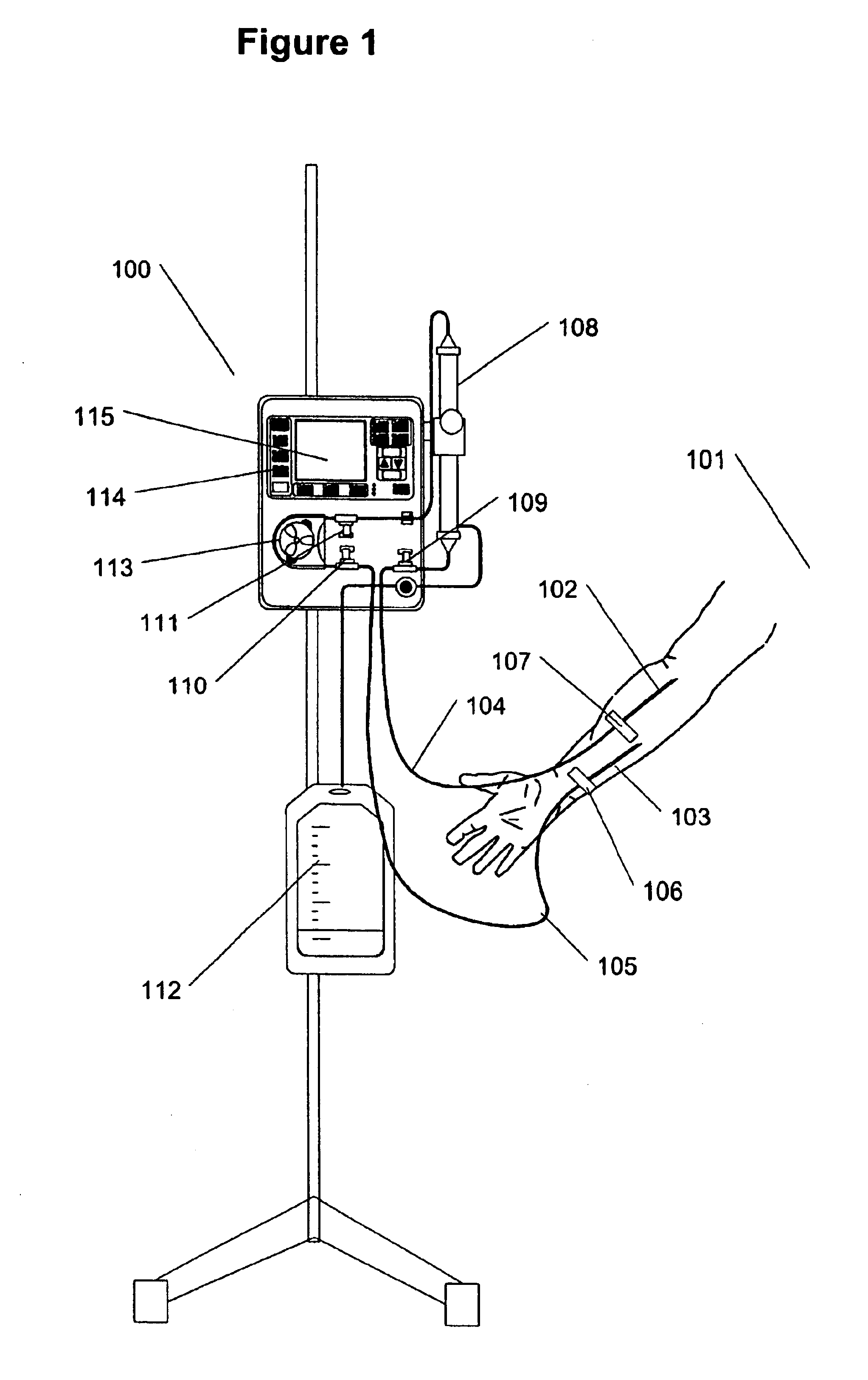
[0086]FIG. 1 illustrates the treatment of a fluid overloaded patient with the present invention 100. Patient 101 can undergo treatment while in bed or sitting in a chair. Patient can be conscious or asleep. To initiate treatment two relatively standard 18G needles 102 and 103 are introduced into suitable peripheral veins (on the same or different arms) for the withdrawal and return of the blood. This procedure is no different from blood draw or IV therapy. Needles and atta...


PUM

PropertyMeasurementUnit
Lengthaaaaaaaaaa
Fractionaaaaaaaaaa
Fractionaaaaaaaaaa

Abstract

A method and apparatus for ultrafiltration of blood operating by removing blood from a peripheral blood vessel at a rate of less than two percent of total cardiac output of a patient, extracting fluid at a rate of 0.1 liter to 1.0 liters per hour while retaining cells and proteins in the blood, and returning the concentrated blood to a secondary blood vessel is disclosed. Blood is removed and returned using small gage needles. As a pump circulates blood from the patient, a filter removes ultrafiltrate from the blood using duty cycle or pump control, and a transparent container collects the removed fluid.

Description

RELATED APPLICATION[0001]This application is related and claims priority to the commonly-owned provisional application Ser. No. 60 / 206,232, entitled “Peripheral Vein Fluid Removal in Heart Failure”, that was filed in the U.S. Patent and Trademark Office on May 23, 2000, and the entirety of which is incorporated by reference herein.FIELD OF THE INVENTION[0002]This invention relates to methods and apparatus for treatment of congestive heart failure (CHF). In particular, the invention relates to the removal of excessive fluids, such as water, in patients suffering from CHF.BACKGROUND OF THE INVENTION[0003]Congestive Heart Failure (CHF) is the only form of heart disease still increasing in frequency. According to the American Heart Association, CHF is the “Disease of the Next Millennium”. The number of patients with CHF is expected to grow even more significantly as an increasing number of the “Baby Boomers” reach 50 years of age.[0004]CHF is a condition that occurs when the heart becom...

Claims


Application Information

Patent Timeline
IPC IPC(8): A61M1/34A61M1/18A61M1/22A61M1/14A61M1/36
CPCA61M1/34A61M1/3612A61M1/341A61M1/361A61M1/1692A61M2205/3393A61M2205/7563A61M2205/50
Inventor LEVIN, HOWARD R.GELFAND, MARKO'MAHONY, JOHNPOLASCHEGG, HANS-DIETRICH
Owner GAMBRO LUNDIA AB
Why Eureka
Try Eureka