Modified diffusion layer for use in a fuel cell system

a fuel cell and diffusion layer technology, applied in cell components, electrochemical generators, transportation and packaging, etc., to achieve the effect of enhancing the cell performan

Inactive Publication Date: 2005-05-10
MTI MICROFUEL CELLS
View PDF23 Cites 47 Cited by
  • Summary
  • Abstract
  • Description
  • Claims
  • Application Information

AI Technical Summary

Benefits of technology

[0015]The present invention is a modified diffusion layer for use on the cathode face of a protonically conductive membrane of a DMFC, which is comprised of a diffusion material that has preferential flow paths incorporated therein which redirect and remove liquid across the diffusion layer and cause the liquid to preferentially flow, in a predetermined manner, usually away from the PCM. The inventive diffusion layer can thus provide a preferential path by which liquid reactants or byproducts may be removed. By providing a means by which fluids present on the cathode face of the fuel cell are removed without the use of pumps or other power consuming devices, the overall efficiency of the fuel cell is enhanced, and the operation of the cell is improved.
[0019]In addition, materials may be selectively chosen for the microporous layer and other components in the cell, to encourage the flow of water (or other liquid byproducts and reactants) in certain predetermined directions within the cell, to further enhance performance of the cell.

Problems solved by technology

After drying and then sintering at the glass transition temperature of the Teflon, the face of the porous coating layer cracks, forming a mud-cracked pattern on the resulting microporous layer.

Method used


Image

  • Modified diffusion layer for use in a fuel cell system
  • Modified diffusion layer for use in a fuel cell system
  • Modified diffusion layer for use in a fuel cell system

Examples


example

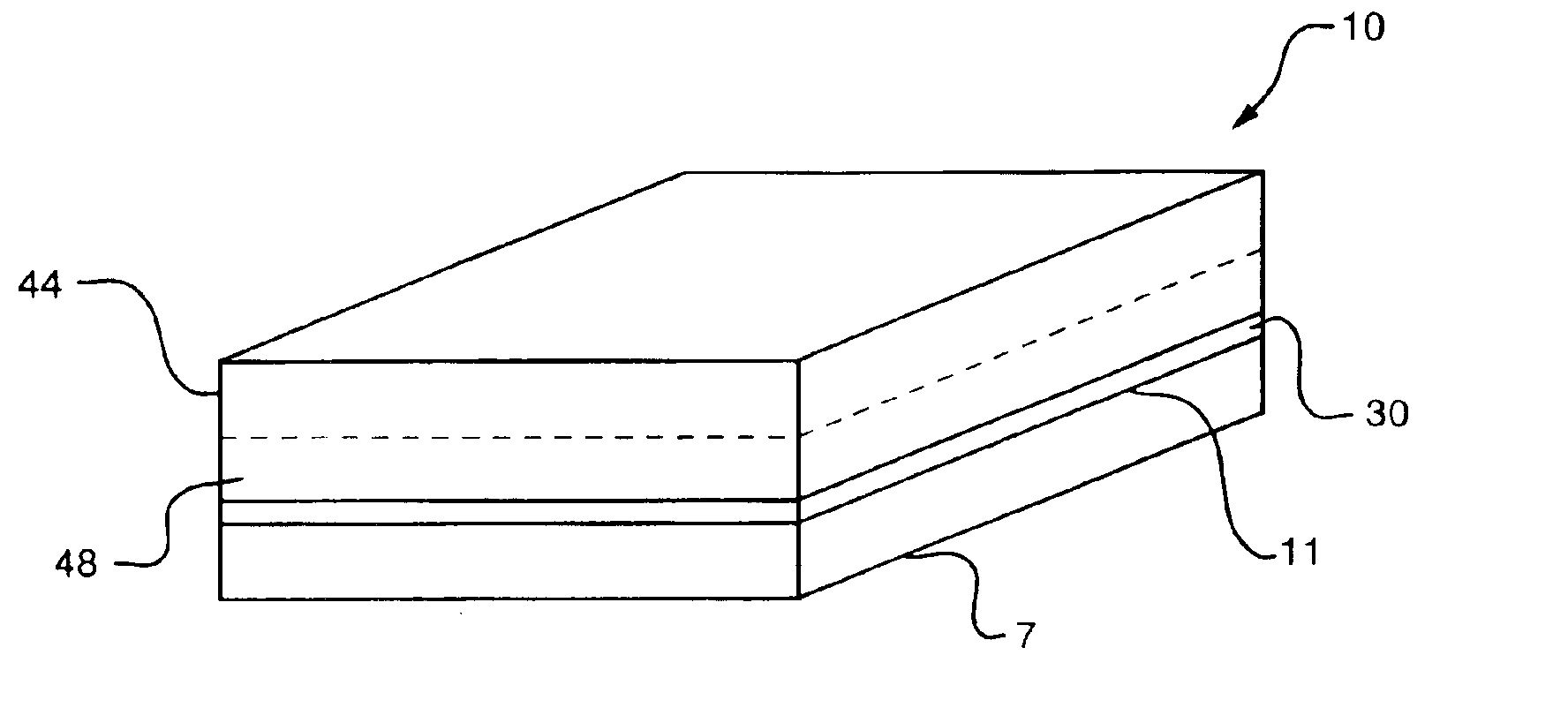
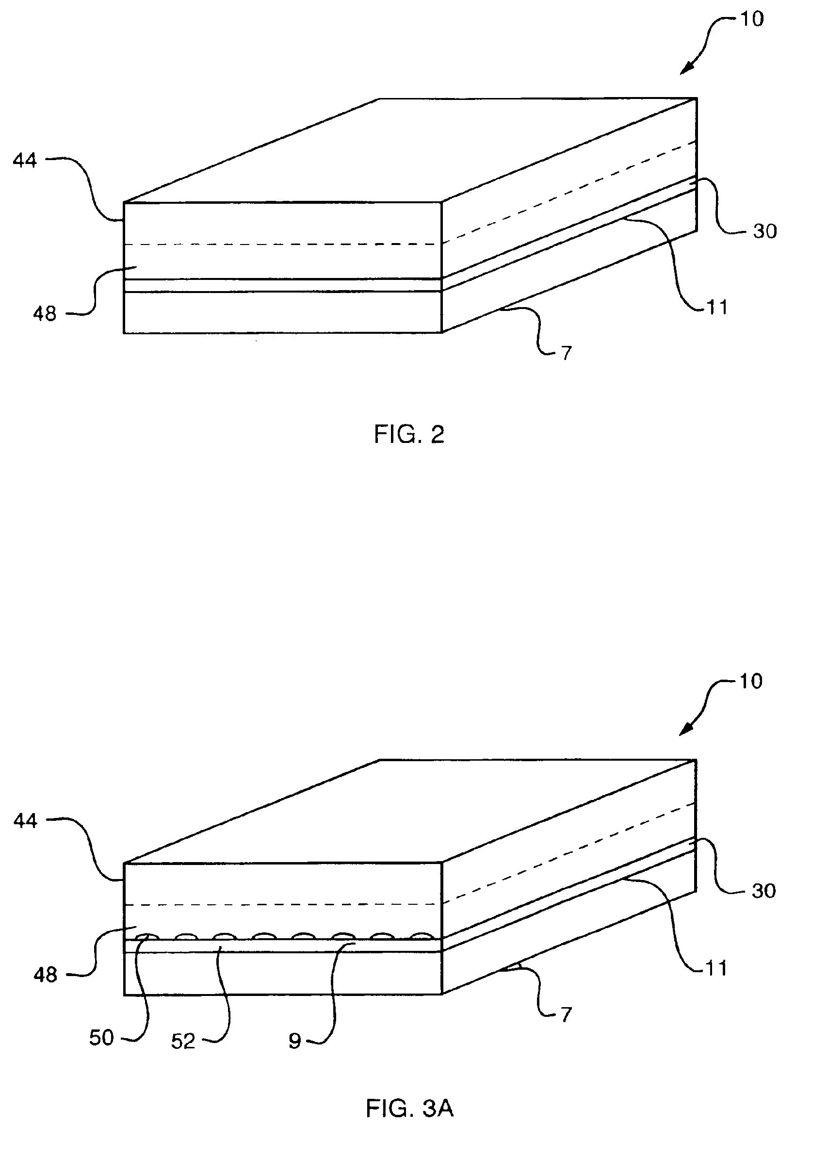
[0044]A diffusion layer was fabricated by employing a substrate formed from a sheet of ELAT diffusion backing, commercially available from the E-Tek division of De Nora N.A., 39 Veronica Avenue, Somerset, N.J. 08873, measuring about 3.162 cm by 3.162 cm. This diffusion layer was comprised of a carbon cloth substrate with a microporous layer comprised of Teflon-bonded high surface area carbon particles. A lattice like pattern was embossed into the diffusion layer using pressure of 10,000 pounds per square inch, the pattern extending to the edges of the diffusion layer. The embossed diffusion layer was then placed in intimate contact with a catalyst coated membrane for use in the membrane electrode assembly of a direct methanol fuel cell.

[0045]The microporous layer tends to form a hydrophobic barrier adjacent the catalyst coated PCM, however, water can still build up near the cathode face of the fuel cell. The embossment in the cathode diffusion layer causes such water to travel along...


PUM

PropertyMeasurementUnit
pressureaaaaaaaaaa
protonically conductiveaaaaaaaaaa
electrically conductiveaaaaaaaaaa

Abstract

A fuel cell diffusion layer providing a preferential path by which liquid reactants or byproducts may be supplied to or removed from a direct oxidation fuel cell is described. The modified diffusion layer will be typically on the cathode side of the fuel cell and its use is to eliminate or minimize flooding of the cathode diffusion layer area, which is a performance limiting condition in direct methanol fuel cells. In accordance with one embodiment of the invention, the diffusion layer includes a substrate that is coated with a microporous layer. A pattern may be embossed into the diffusion layer, to create preferential flow paths by which water will travel and thereby be removed from the cathode catalyst area. This avoids cathode flooding and avoids build up of potentially destructive pressure by possible cathodic water accumulation. This also provides a means for collecting cathode water for redirection In accordance with another aspect of the invention, the preferential path is established by applying a thicker microporous layer to the carbon cloth or carbon paper and drying it in such a fashion so that when it dries, the surface of the microporous layer cracks to provide the pathways.

Description

BACKGROUND OF THE INVENTION[0001]1. Field of the Invention[0002]This invention relates generally to direct oxidation fuel cells, and more particularly, to diffusion layers for such fuel cells.[0003]2. Background Information[0004]Fuel cells are devices in which an electrochemical reaction is used to generate electricity. A variety of materials may be suited for use as a fuel depending upon the materials chosen for the components of the cell. Organic materials, such as methanol or natural gas, are attractive choices for fuel due to the their high specific energy.[0005]Fuel cell systems may be divided into “reformer-based” systems (i.e., those in which the fuel is processed in some fashion to extract hydrogen from the fuel before it is introduced into the fuel cell system) or “direct oxidation” systems in which the fuel is fed directly into the cell without the need for separate internal or external processing. Most currently available fuel cells are reformer-based fuel cell systems. H...

Claims


Application Information

Patent Timeline
Patent Type & Authority Patents(United States)
IPC IPC(8): H01M4/88H01M4/96H01M8/10H01M4/86H01M4/90H01M4/92
CPCH01M4/8605H01M4/8807H01M4/8817H01M8/1004H01M8/1009H01M4/96H01M4/92Y10T428/30Y02E60/523Y02E60/50
Inventor BECKMANN, GERHARDREN, XIAOMINGMUTOLO, PAUL F.KOVACS, FRANK W.GOTTESFELD, SHIMSHON
Owner MTI MICROFUEL CELLS
Why Eureka
Try Eureka